
OSSO: current state (Nov 5, 2026)
The working design as of today. Frozen snapshots are in the timeline; the last frozen snapshot is listed there.
1. Machine: run 42
Run 42: the tray bridge and hangers are gone so the strip tray is open at the front, and the needle sensor, turntable, up-camera and cleaning pod sit in one row in front of the PCB. Same 23 strips and 20 pockets. See the machine page and the 3D viewer.
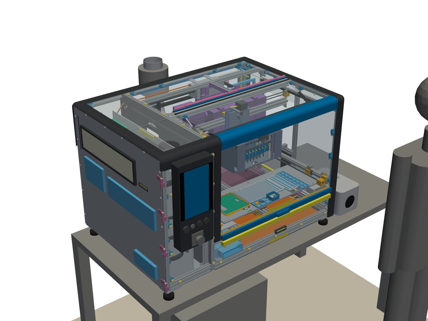
Run 41
Run 41: the X-carriage plates and the gantry finish the 180 degree rotation that run 40 started on the needle tray; cartridge swaps still face the front. See the archive.
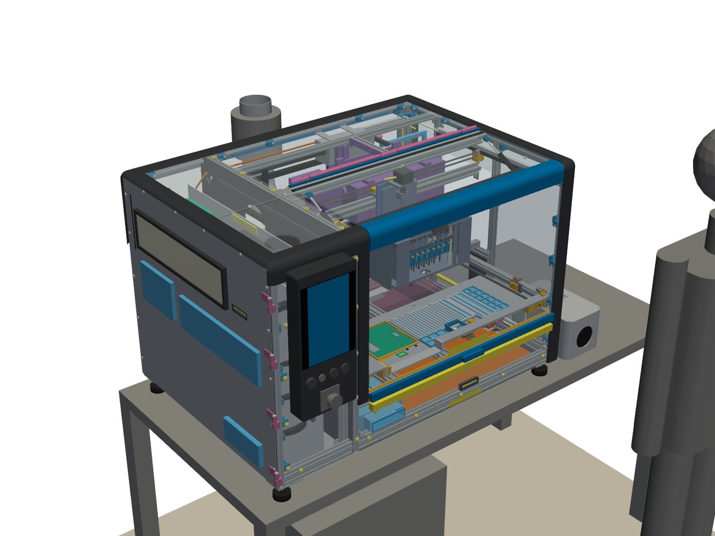
Run 40
Run 40: the needle tray is rotated 180 degrees so it faces the other way; cartridge swaps still face the front. The PCB, laser and 23-strip tray stay as in run 39. See the archive.
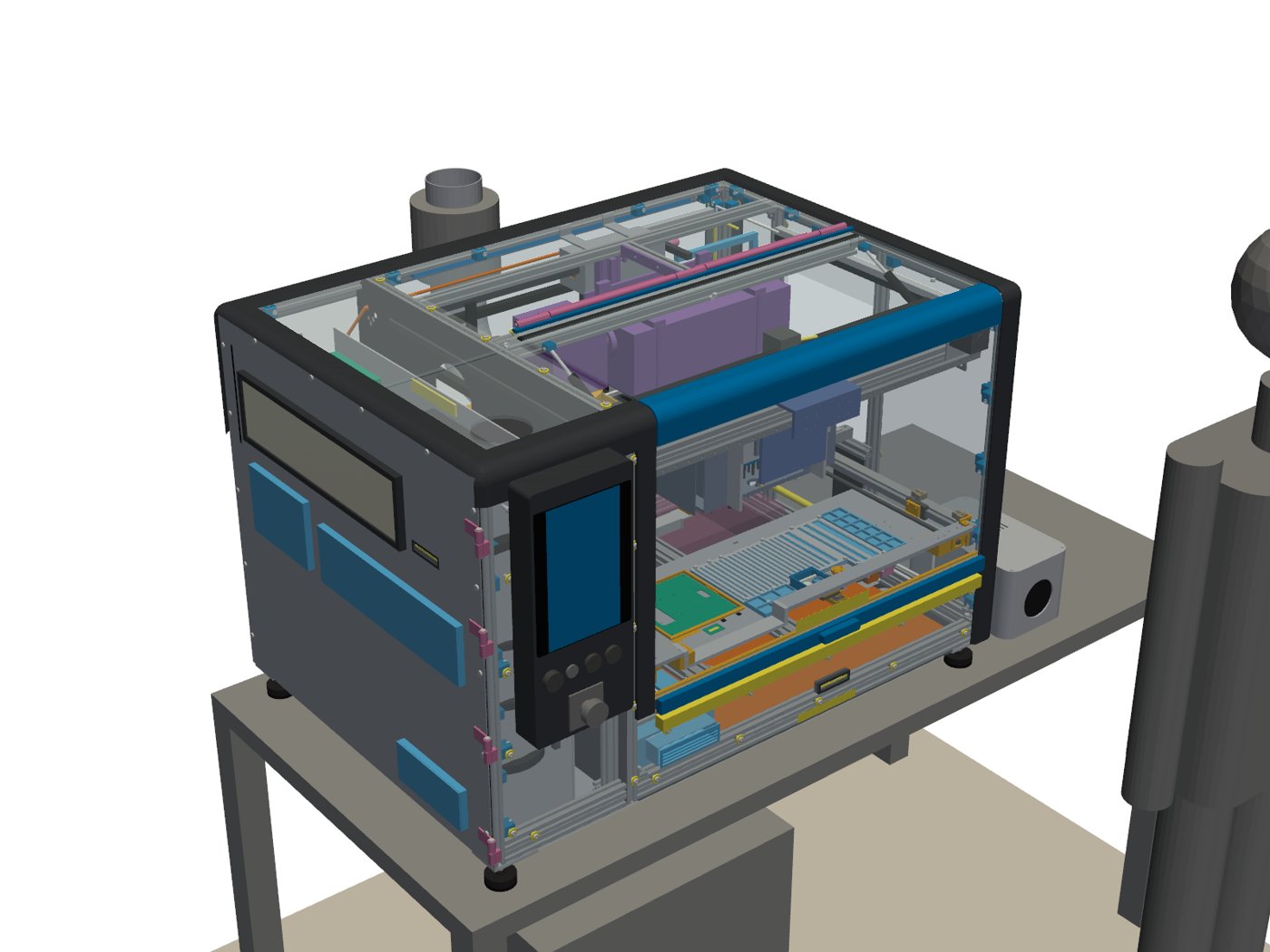
Run 39
Run 39: the needles swapped onto the opposite 20 mm seats, the PCB and laser moved 60 mm to the left, and the strip tray grew to 23 strips (8 to 24 mm) plus 20 open pockets. See the archive.
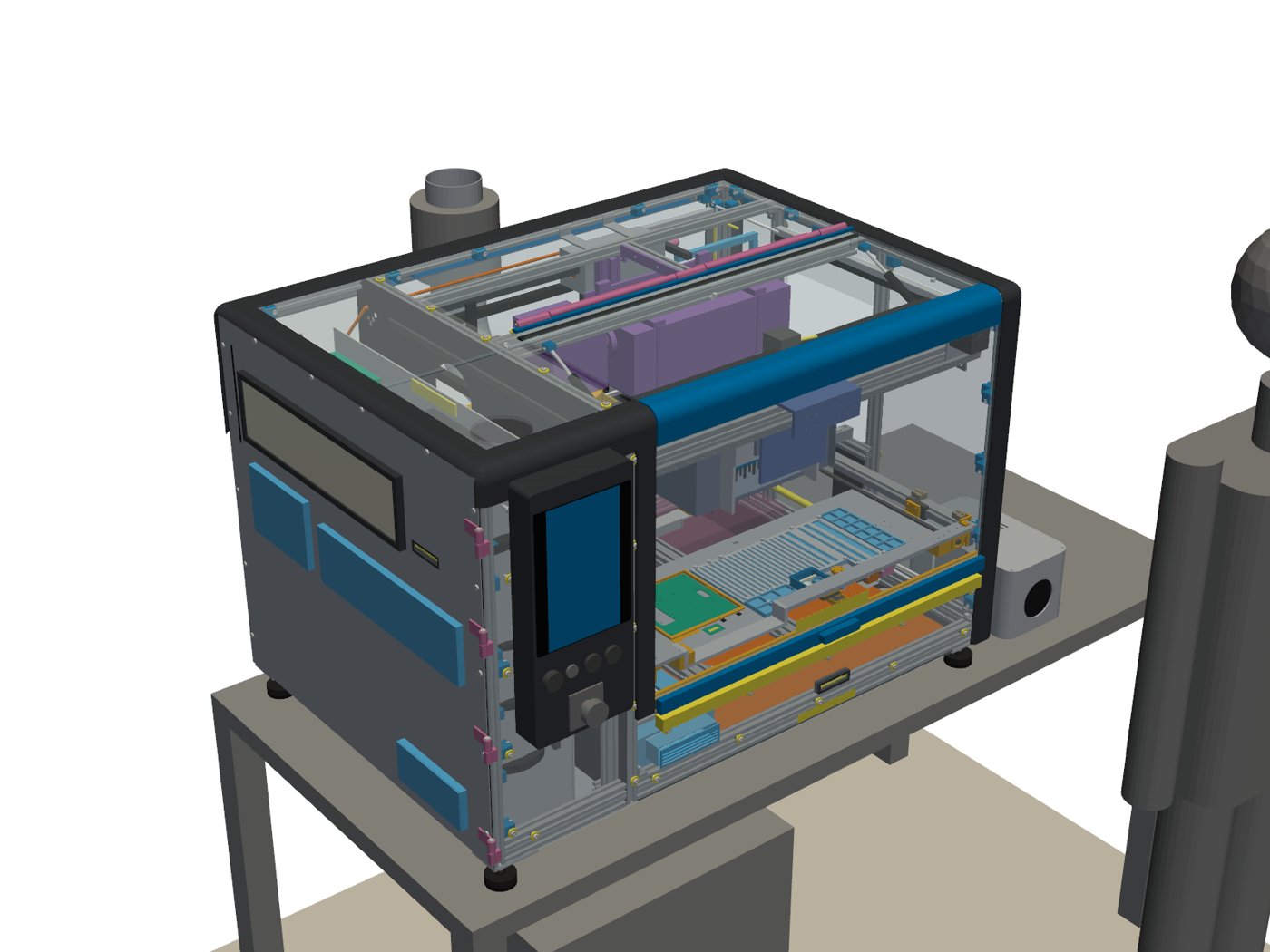
Run 38
Run 38: the PCB and laser moved 30 mm to the left, the head travels further left, and the strip tray grew to 18 strips (8 to 24 mm) plus 16 open pockets. The cabinet fans moved outside the work area. See the archive.
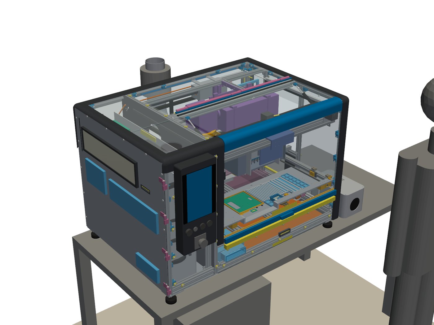
Run 33
Run 33: the MiniPC is its own assembly on the bench next to the machine, the air system serves only the needles (one pump, two tanks, five valves), and the cam slide has a 200 mm stroke for the full 170 mm cam stroke. See the machine page and the 3D viewer.
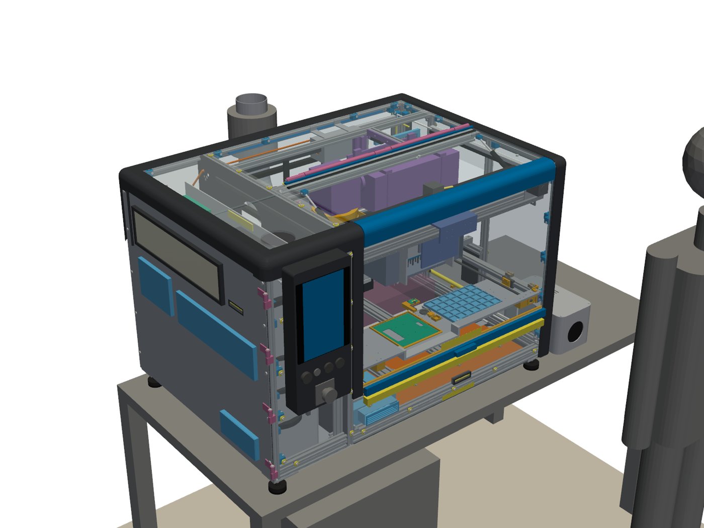
Run 32
Run 32: the PCB holder moved 7 mm left (the most that keeps full needle reach on the board) with the laser, galvo, hood and exhaust following it, the single tray grown to 199 x 162 mm (7 x 6 pockets), and a fixed laser hood with a soft silicone band instead of drop cylinders. See the machine page and the 3D viewer.
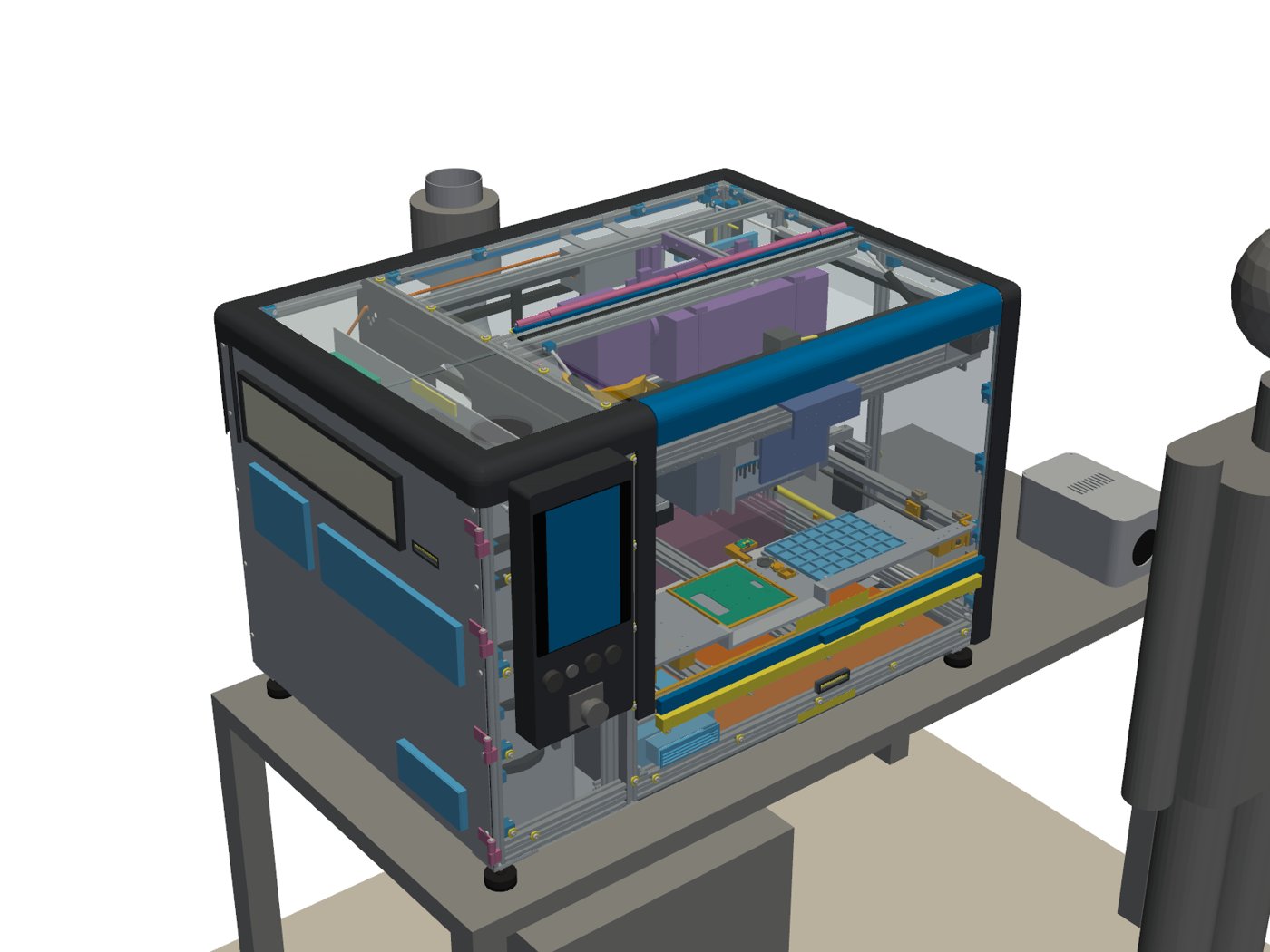
Run 31
Run 31: an eight-tool head at 20 mm pitch with front-loading cartridges, the PCB at the far left and one 42-pocket tray on the right, a compact 24 V vacuum pump with a 1.0 bar relief valve, and zero clashes in the full interference check. See the machine page and the 3D viewer.
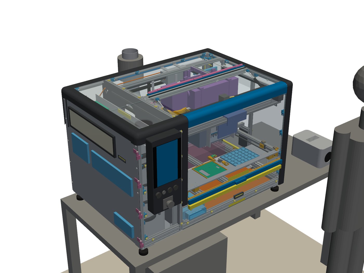
Run 30
Run 30: every outside connection on one rear service panel (host USB-C on the front), vacuum on the needles that reach every tray cell, a standard 4 in exhaust, the touchscreen back in the front pod, the chiller centred under the machine and no foot pedal. See the archive.
Run 26
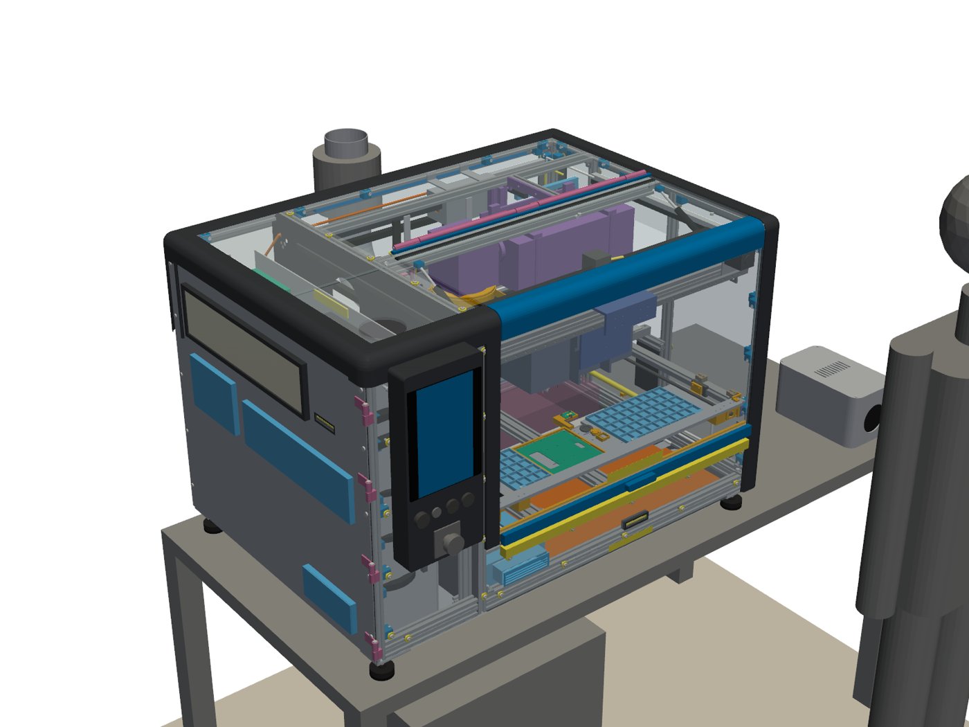
Run 26: bigger flexible part trays on each side of the PCB, the air filter unit and the optional lube pump moved inside, flush tube levels, and a marked free space below the laser. See the run 26 machine page. Before that, run 25: the PCB, laser and hood moved right so every needle and the hot-air tip reach the whole board and the whole through-hole tray; QR tags on the part trays and on each job board; a fire watch on the fumes duct (see the archive).
Run 22
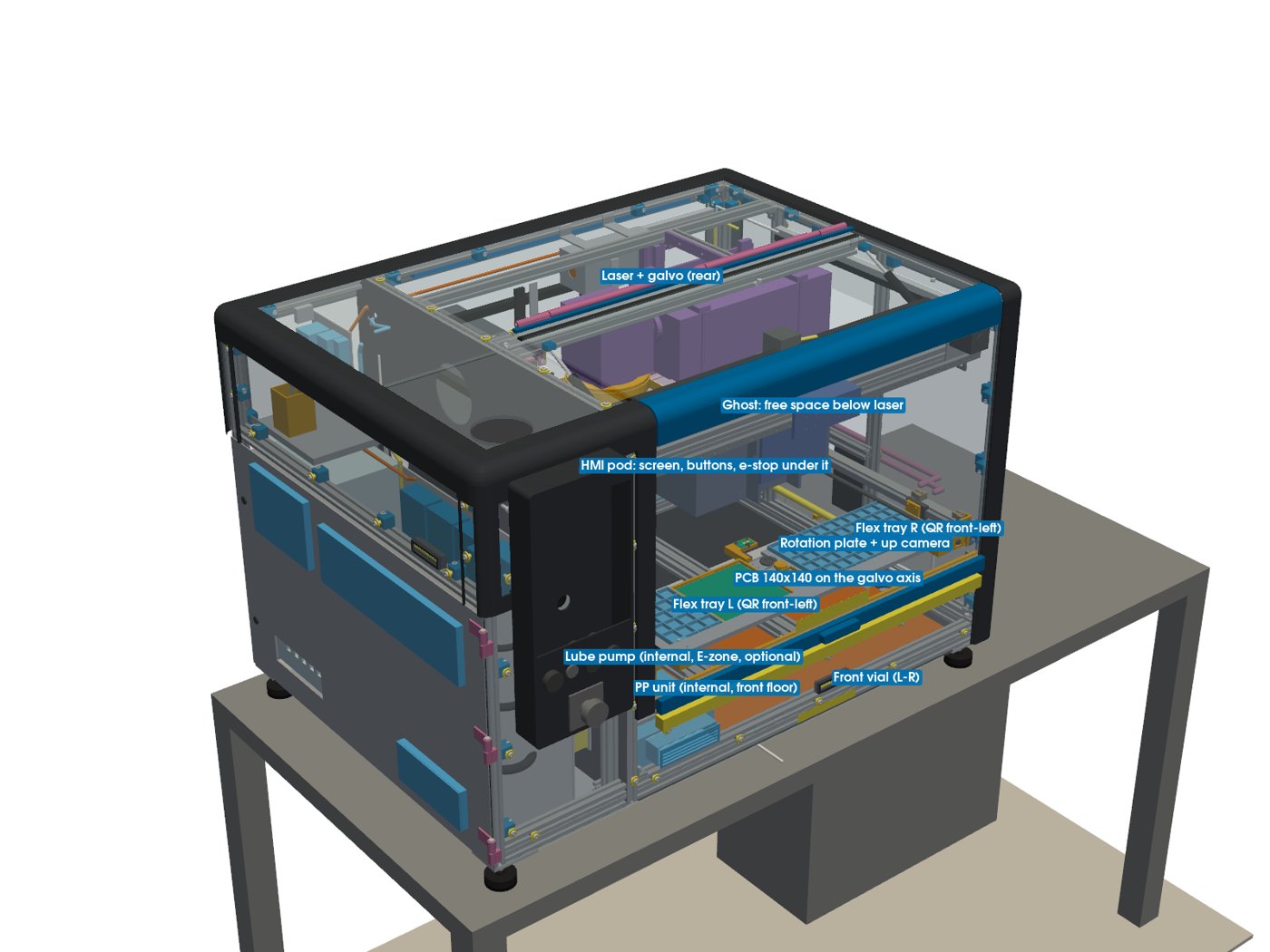
Run 22: a front HMI pod (touchscreen under the vent exit, buttons and e-stop right below) and a one-slide hood quick-disconnect with kinematic seats, a fixed face-sealed exhaust and a hood-sealed interlock. See the run 22 machine page.
Run 20
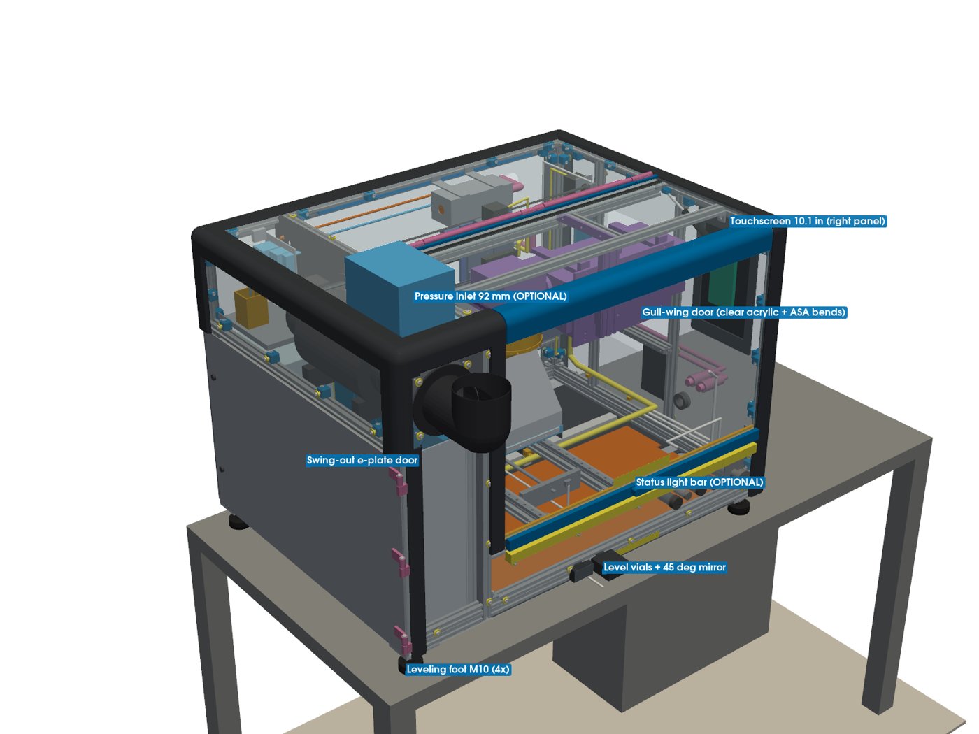
Run 20: laser hood v1f, enclosure v2 (clear acrylic, T-slot, ASA corner covers, touchscreen on the right panel), gull-wing door, swing-out electronics plate and leveling feet, plus the optional positive-pressure module and status light bar. See the run 20 machine page.
Run 19
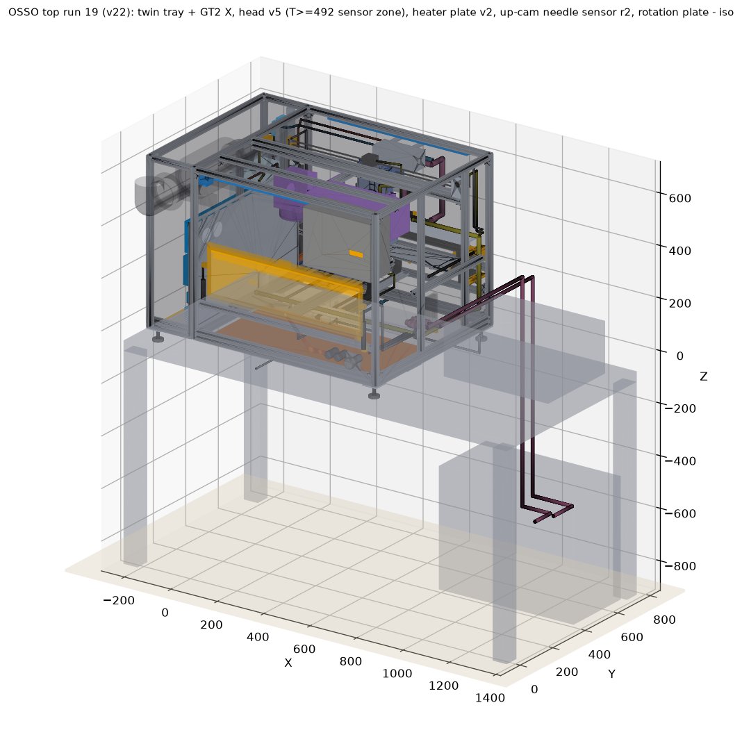
Run 19 (snapshot v22): twin tray + GT2 belt X, head v5 with the T ≥ 492 mm needle-sensor zone rule, heater plate v2, up-camera needle sensor r2 and the rotation plate. See the run 19 machine page.
Run 16
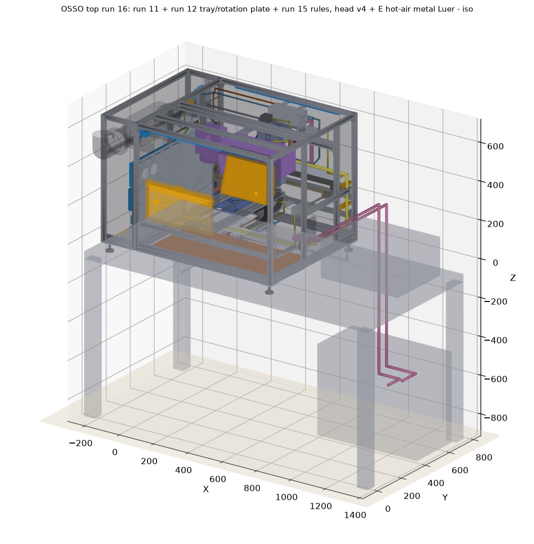
The bench-top run 11 unit with head v4 (all-metal Luer tips, N1 ball drop only) and the hot-air (E) nozzle on the head-front bracket (approved), with an E-only Z soft limit of 327.7 mm at T ≥ 462 mm (approved). Details, animations, the views deck and downloads are on the run 16 machine page.
2. Frameless interposer r5b
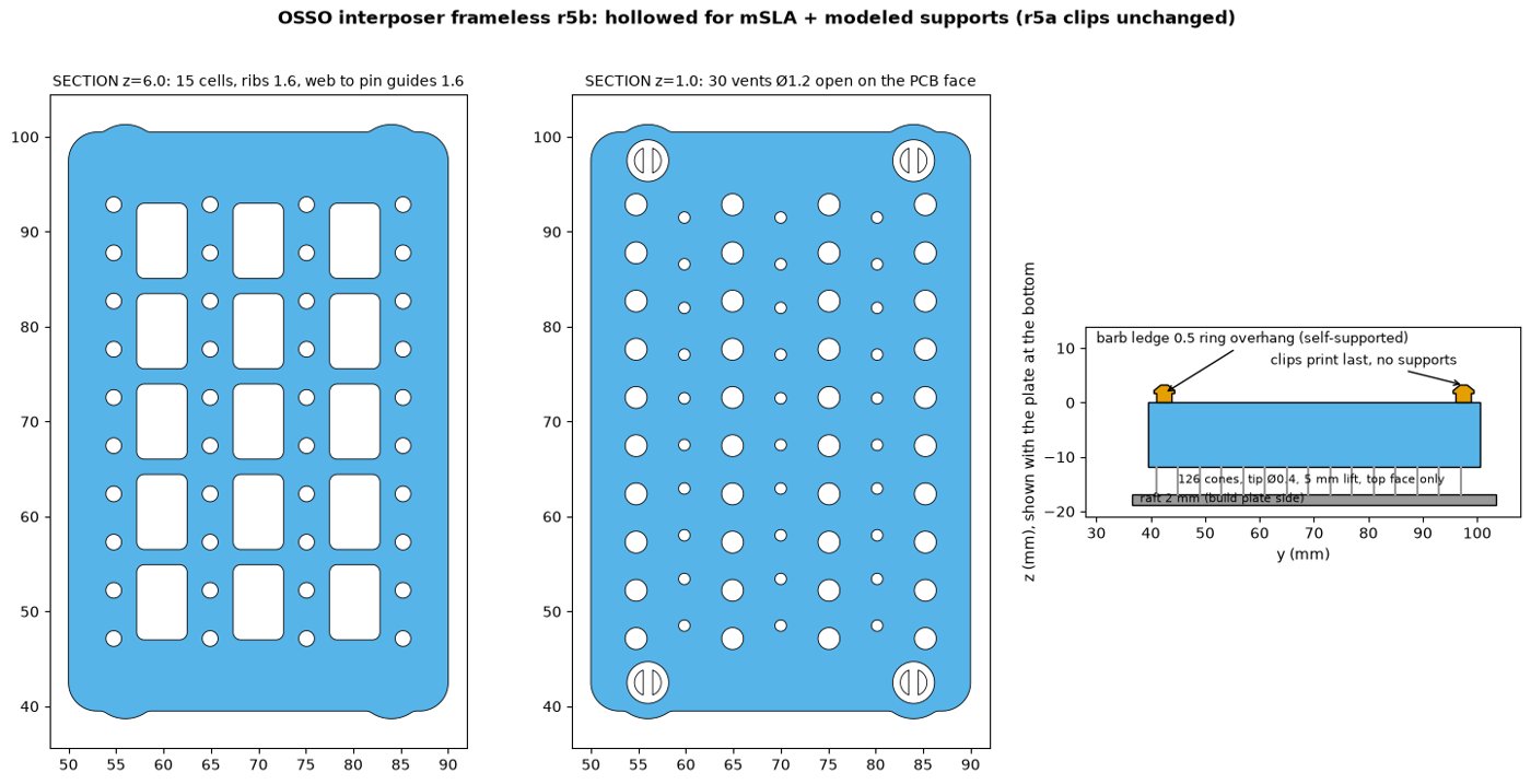
The r5a body, pins and snap clips unchanged, now hollowed (15 internal cells, about 15% less resin) with 30 vents of 1.2 mm on the PCB face so the cells drain and can be flushed. Printed top face toward the plate with 126 modelled support cones on the top face only, so the clips print clean. Minimum wall 1.6 mm. Sand the support nubs below 0.1 mm.
- 2026_10_28_OSSO_interposer_frameless_r5b.step
- 2026_10_28_OSSO_interposer_frameless_r5b.3mf
- 2026_10_28_OSSO_interposer_frameless_r5b_print_supported.3mf
- 2026_10_28_OSSO_interposer_frameless_r5b.stl (zip)
- 2026_10_28_OSSO_interposer_frameless_r5b_print_supported.stl (zip)
- 2026_10_28_OSSO_interposer_frameless_r5b.glb
- README (r5b)
3. Interposer assembly jig v1
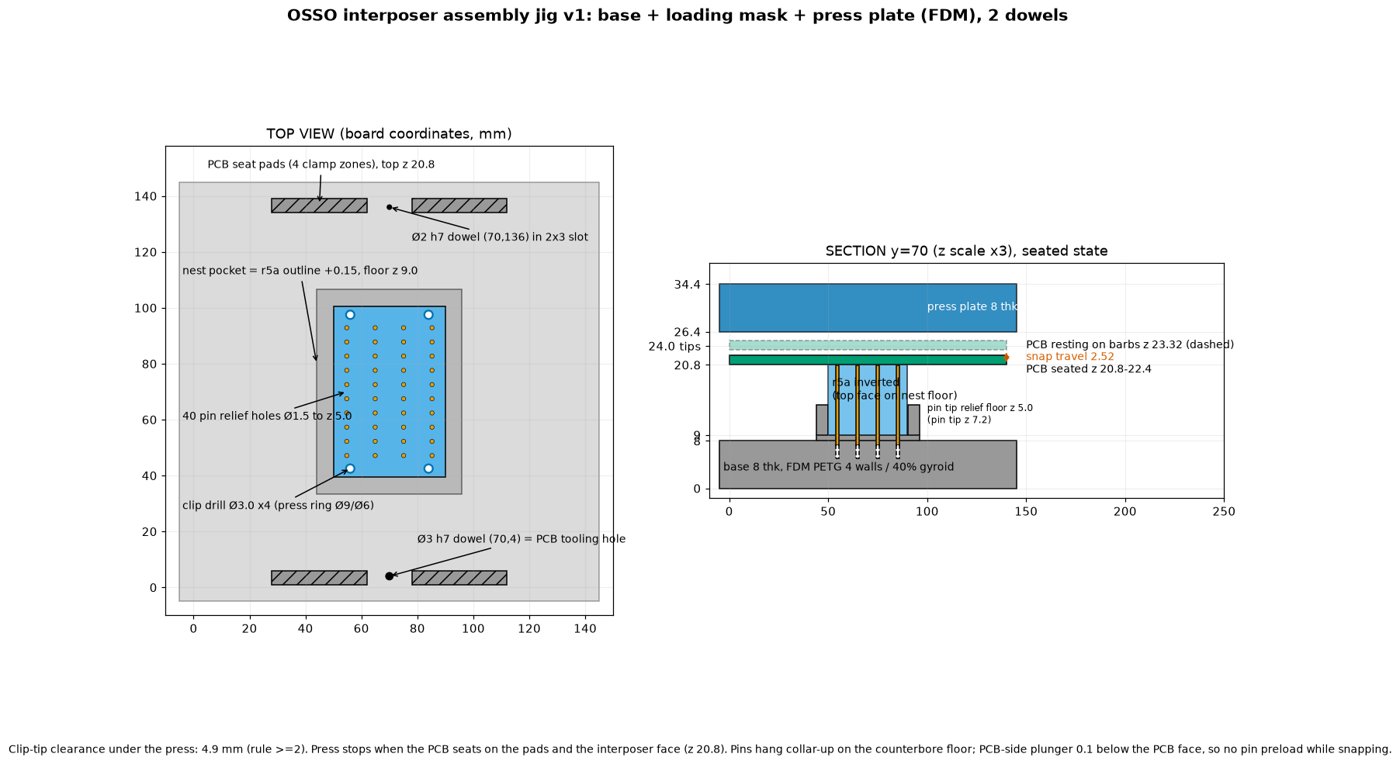
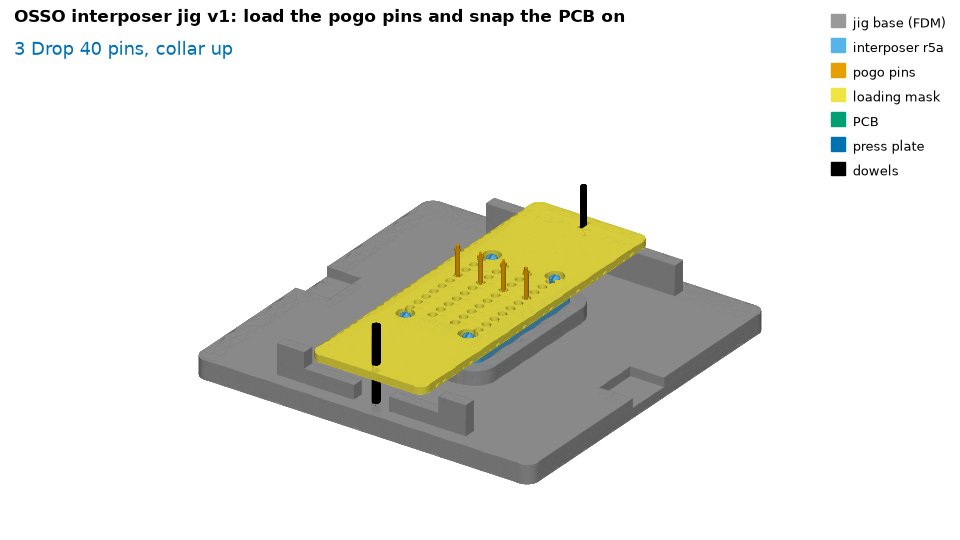
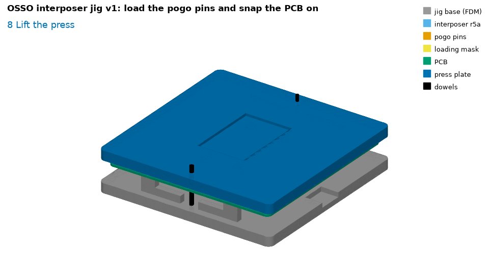
Three printed PETG parts (base nest, loading mask, press plate) plus two dowel pins. Drop the 40 pogo pins through the mask, set the PCB on the dowels, and press 2.52 mm to snap the clips. Estimated snap force 11 to 17 N (not measured).
- 2026_10_28_OSSO_interposer_jig_v1.step
- 2026_10_28_OSSO_interposer_jig_v1_base.stl
- 2026_10_28_OSSO_interposer_jig_v1_mask.stl
- 2026_10_28_OSSO_interposer_jig_v1_press.stl
- 2026_10_28_OSSO_interposer_jig_v1.glb
- Snap force estimate (JSON)
- README (jig v1)
4. Boards: top/bottom v1n and middle v3e
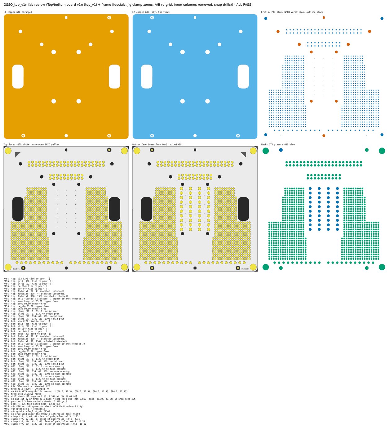
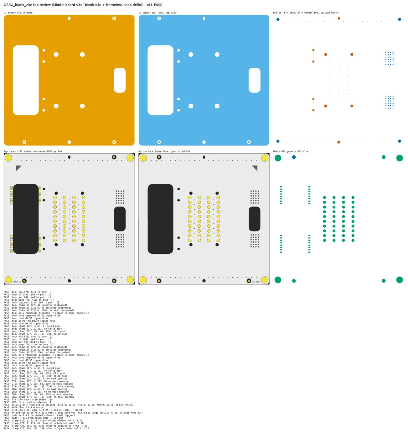
140 x 140 mm, 1.6 mm FR4, 2 layers, 1 oz, ENIG, black mask, white silk flood. Zero-clearance copper pour with every pad tied in; only the fiducials are isolated. Four 3.0 mm snap holes with 5.0 mm copper-free voids for the interposer clips. Both boards pass the fab review. v1n: 5 boards being ordered. v3e: not ordered.
- OSSO_top_v1n Gerbers (zip) (zip)
- 2026_10_28_OSSO_top_v1n_ghost.step
- 2026_10_28_OSSO_top_v1n_ghost.glb
- OSSO_blank_v3e Gerbers (zip) (zip)
- 2026_10_28_OSSO_blank_v3e_ghost.step
- 2026_10_28_OSSO_blank_v3e_ghost.glb
- README (frameless r1 fab)
5. Solder process (test baseline)
These are starting values for the coupon tests, which will set the final numbers. Rule: one ball size for every part, 0.25 mm. One size per job, never switched mid-job; the volume is tuned by ball count.
- Minimal tin: a flux-loaded wick wipe leaves a thin, flat layer of about 10 to 20 µm that wets the pad and gives an even surface for placement.
- Pick-and-place into one tacky flux patch per terminal.
- Solder balls after placement: 0.25 mm SAC305 balls (each a fixed 0.00818 mm³) go at the outer toe of each terminal, and at the heel of gull-wing leads where there is room, outside the part body, so the solder forms the visible fillet. Then one reflow.
Baseline balls per terminal: 0402 2, 0603 4, 0805 8, 1206 14 (three toe rows), SOT-23 4, SOIC 6 (4 toe + 2 heel), QFN 1, for about 100 to 120% of a normal paste fillet at 15 µm of tin. The count is tunable per part: one ball more or less per coupon round, based on the fillet. The 1206 third row fits the current pad (0.85 mm of toe needed, 0.88 mm exposed). Some footprints need a longer toe pad: 0402 +0.02, 0603 +0.105, SOT-23 +0.325, SOIC +0.12, QFN +0.07 mm. All values are subject to testing. Single-step reflow is deprecated.
6. PCB rules
Added 2026-10-28 (consistency review A11, approved by the designer).
Pogo pads and vias
- Every pogo pad is tied into the copper pour with zero clearance. This is how circuits reach the board interior and the adjacent boards through the interposer.
- A pogo pad never gets a via of its own (no via-in-pad, no dedicated via next to it), because the pad's net on the bottom need not match the pad on the top.
- When a top pad and a bottom pad must connect, route each through the engraved pour to an EXISTING via of the fixed via grid.
- Only the fiducials are isolated in the factory copper. All other isolation is made by laser engraving the pour.
- Fab check (to add to check_frameless_r1.py / check_v3c.py): fail if any PTH via centre lies within (pogo pad R + via pad R + 0.15) of a pogo pad centre.
Related, confirmed 2026-10-28
- Interposer snap: the barb seat keeps its solder mask. Check the snap Ø5.0 copper-free void to the nearest pogo PAD edge ≥ 0.3 (there is no pogo isolation ring).
- Tooling: Ø3.0 non-plated hole at (70,4) and a 2.0x3.0 non-plated slot at (70,136), long axis Y (v1n = v3c).
- Fiducials A (22,4), B (118,4) Ø0.4 plated; C (118,136) top / C' (22,136) bottom.
- Vias: Ø0.3 drill / Ø0.6 pad, tented.
- Clamp only in the 4 jig clamp zones (project/pcb/fab/v3c_blank/JIG_HOLD.md); never on ENIG.
Job QR patch (PR-QR, added 2026-11-02, run 25 / JQR-01)
- Every job PCB carries a job QR patch on BOTH sides, mirrored, at board X 66-74, Y 9-17 (8x8, on the flip axis x = 70, so top and bottom occupy the same board XY). This is the fiducial-free spot at the near edge closest to the angled crosshair camera.
- Keep 1.0 clear of the patch: no vias, pogo pads, fiducials, tooling hole or clamp zones. Checked against v3c: edge vias y 7.5 (gap 64.92/75.08), via grid starts y 14.12 (none near x 70), tooling hole (70,4), fiducials A (22,4) and B (118,4), clamp zones Z1/Z2 x 27-63 / 77-113 y 1-6, power corners.
- No custom stencils or per-job masks, ever (SR-033).
Companion boards (PR-CB, added 2026-11-03, run 31 / SR-053)
- A companion board that the machine places with N8 (fixed 6-8 mm soft silicone cup) must weigh 50 g or less and carry a flat, bare PnP target at its centre of mass: a 10 mm diameter circle minimum (12 mm preferred), no parts, vias, text or solder mask openings inside it, with a silkscreen outline and the label "PnP" next to it.
- N8 hold check: 7 mm cup at -70 kPa gives about 2.7 N theoretical (about 1.3 N at a 50 % seal factor) against 0.49 N for a 50 g board: SF about 2.7 with the seal factor, at the head accelerations used for picks. Heavier boards, boards without the target, or a target outside N8 reach (PCB X 263-390) are placed by hand.
Volume refactor (PR-VR, added 2026-11-04, run 35 / SR-058)
- A fully tested OSSO PCB with its interposer stack can be refactored by the OSSO software into a single multi-layer PCB, with new sizing and port (connector) locations, for volume manufacturing by a fab. This refactored multi-layer PCB is the final destination of the OSSO prototyping workflow: it is sized and its ports placed to meet the packaging constraints of the final product. Design intent only; no CAD change in run 35.
Open items
- Hot air: the E nozzle is now on the head-front bracket (run 16). Re-plumb and test the heater branch before powering it.
- Coolant coupler size is a placeholder until the chiller fittings are known.
- The 50 mm service gap under the machine is kept (decided); it raises the screen height by 30 mm. Leave about 80 mm behind the machine.
- Coupon tests set the final values: tin flatness (10 to 20 µm), ball count per part (baseline, one less, one more), 0402 and QFN toe-ball bridging (QFN leaves 0.225 mm to the next pad), 0402 tilt and tombstones.
- Footprint toe extensions to confirm: 0402 +0.07, 0603 +0.205, SOT-23 +0.125, QFN +0.12 mm.
See the to-do list, decisions and journal.