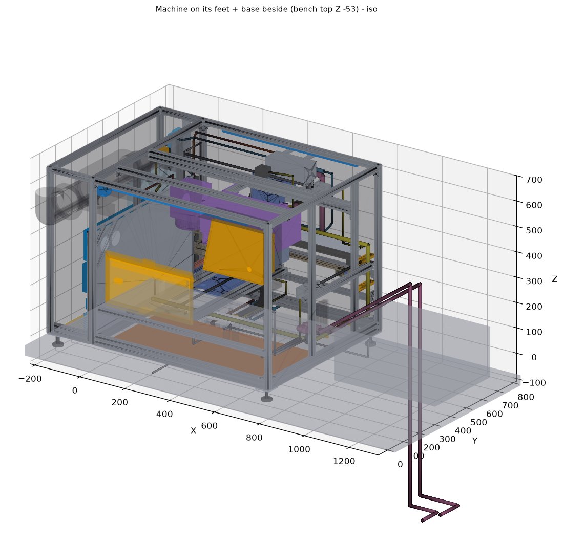
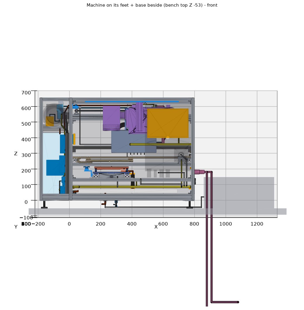
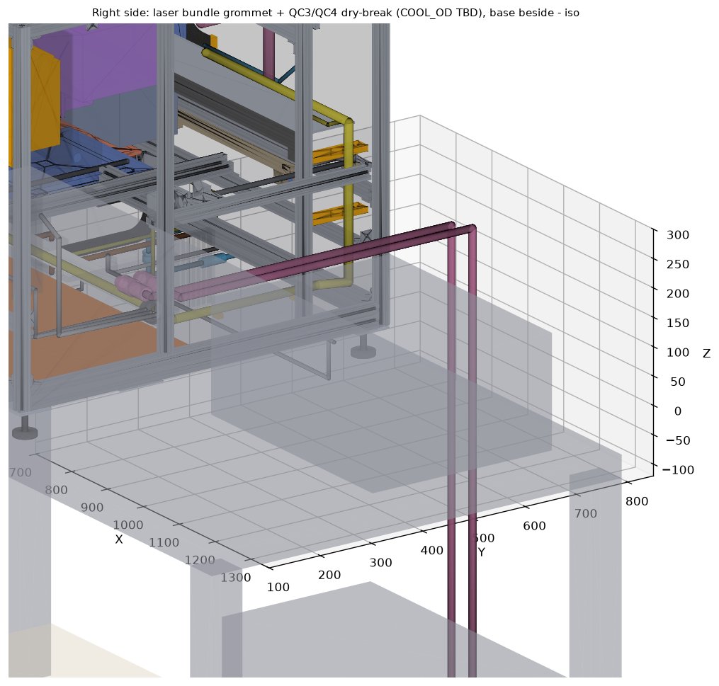
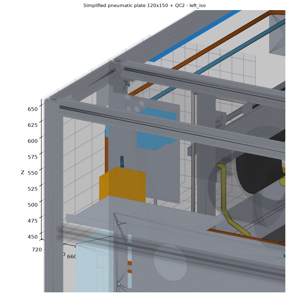
Run 42: open tray front, stations grouped next to the PCB WORK IN PROGRESS
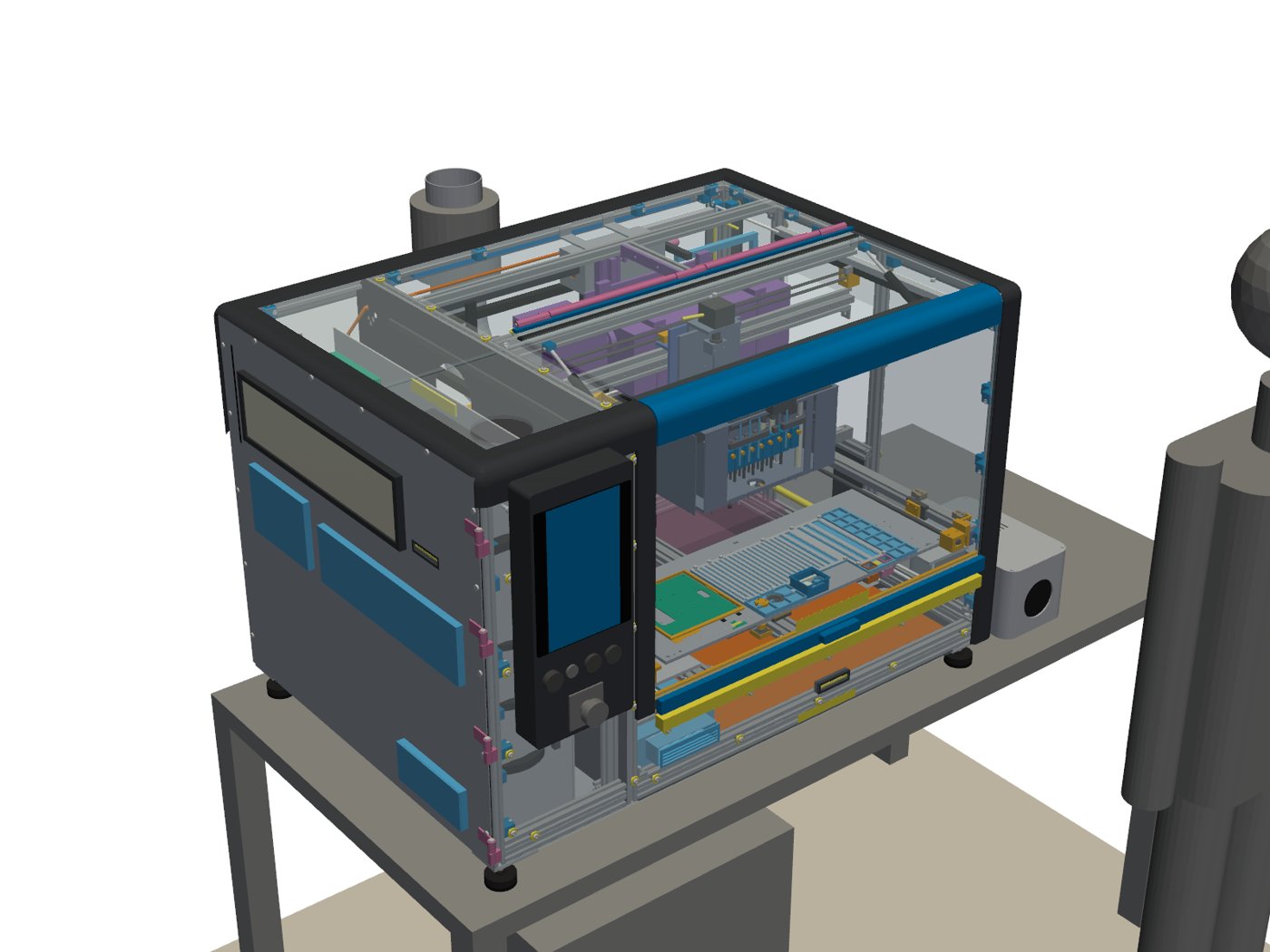
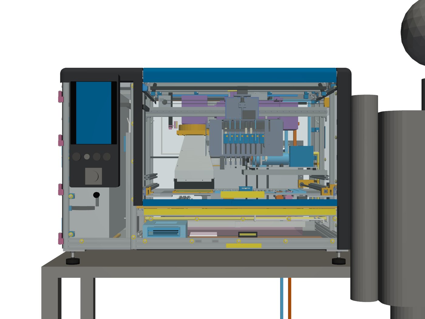
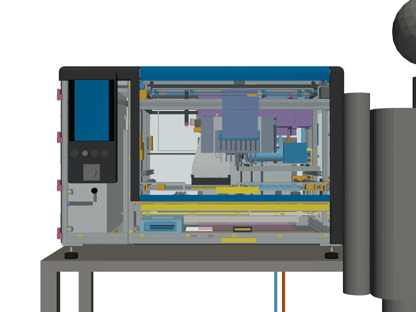
Run 42 (Nov 5, 2026) is the current OSSO machine. The tray bridge and hangers are gone so the operator can reach the strip tray from the front, and the needle sensor, turntable, up-camera and cleaning pod now sit in one row in front of the PCB and tray.
What's new in run 42
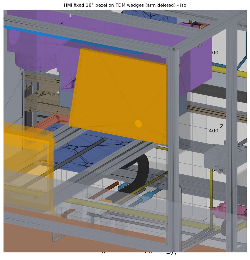
- Open tray front. The tray bridge (outer and centre spans, step risers) and the left and right hangers are removed. Two flat 6 mm laser-cut aluminium arms (X 55 to 150 and 650 to 745) under the carrier, each held by 4 x M5 screws, now carry the front of the carrier. Nothing crosses in front of the tray, and the left hanger overlaps are gone. The moving tray is about 0.31 kg lighter. Support stiffness comes from hand calculations only and has not been validated.
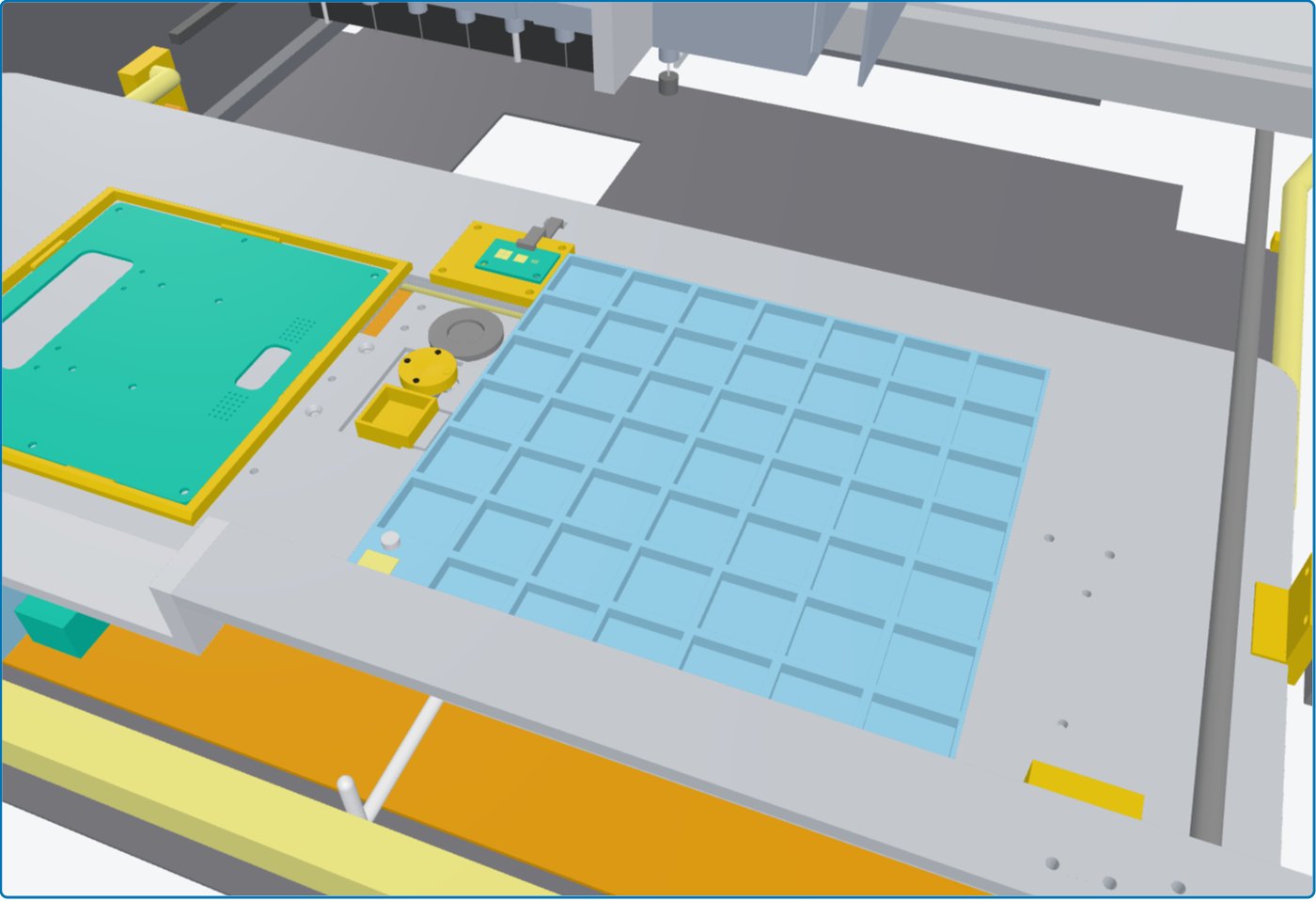
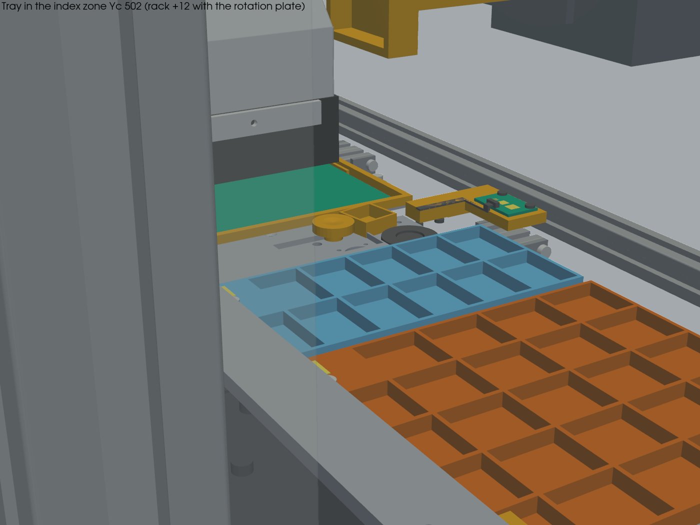
- Station row in front of the PCB. Needle sensor pads at X 262, turntable at X 331, up-camera at X 361, cleaning pod at X 401 to 449 (all at Y 52 to 70). The turntable group is turned 180 degrees and moved 168 mm left. The index rack sits on a new 3 mm seat on top of the right Y-beam, so it still turns the plate (32-step detent), now on the outward stroke. The hood band stays clear (the plate is 12.5 mm from the band).
- Capacity unchanged. 23 strips and 20 open pockets as in run 41. N4 reaches 13 of 20 pockets, N5 and N8 reach 6 of 20.
- Checks. Static interference: 0 hits. Unintended contacts inside the tray assembly: 0. Every intended contact (thumb screws, sensor screws, rack screws) is listed by name. All door, panel, tray and head sweeps: 0 clashes (0.5 mm minimum gap past the hood band). All 8 needles reach every station inside the soft limits.
- Cycle time, reported honestly. Model: X 300 mm/s at 3 m/s2, Y 200 mm/s at 2 m/s2, 0.08 s settle. For a part that only needs a camera check: 1.647 s in run 41 and 1.418 s in run 42. For a part that has to be turned on the plate, moves alone: 2.023 s in run 41 and 1.651 s in run 42. On top of that comes the index trip for each turn (the tray drives to the rack and back), 3.04 s in both runs. The old figure (1.536 s/part) left out acceleration and the index trip.
Renders (run 42)
3D viewer
Open the run 42 model in the 3D viewer: saved views, animations, explode, X-ray, section planes, part tree with isolate and hide, measure, earlier versions, and shareable view links.
Animations (run 42)
The animations play inside the 3D viewer, each from its own saved view:
- Gantry and head moves (X, Y, Z)
- Needle actions (cam slide, N3 to N7)
- Turntable index (rack + detent, 2 x 90 deg)
- Tray picks (N4: cam, Z drop, pick, place on the PCB)
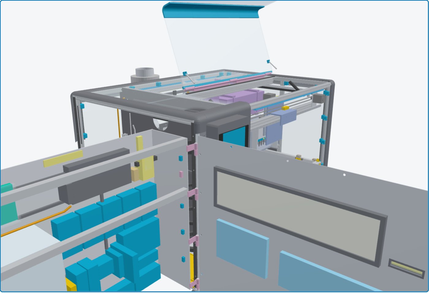
- Gull-wing door (hinge + gas struts)
- Electronics door swing (detents 90 / 180)
Downloads (run 42)
Archive
Earlier runs, newest first. Each one was the current machine in its day.
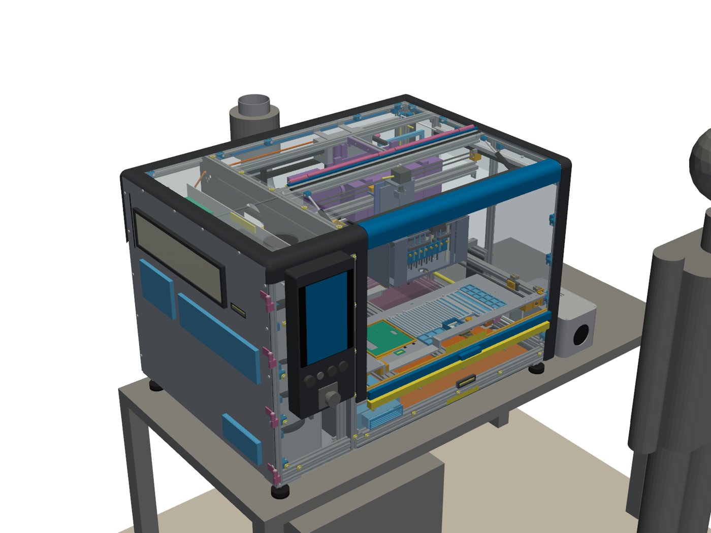
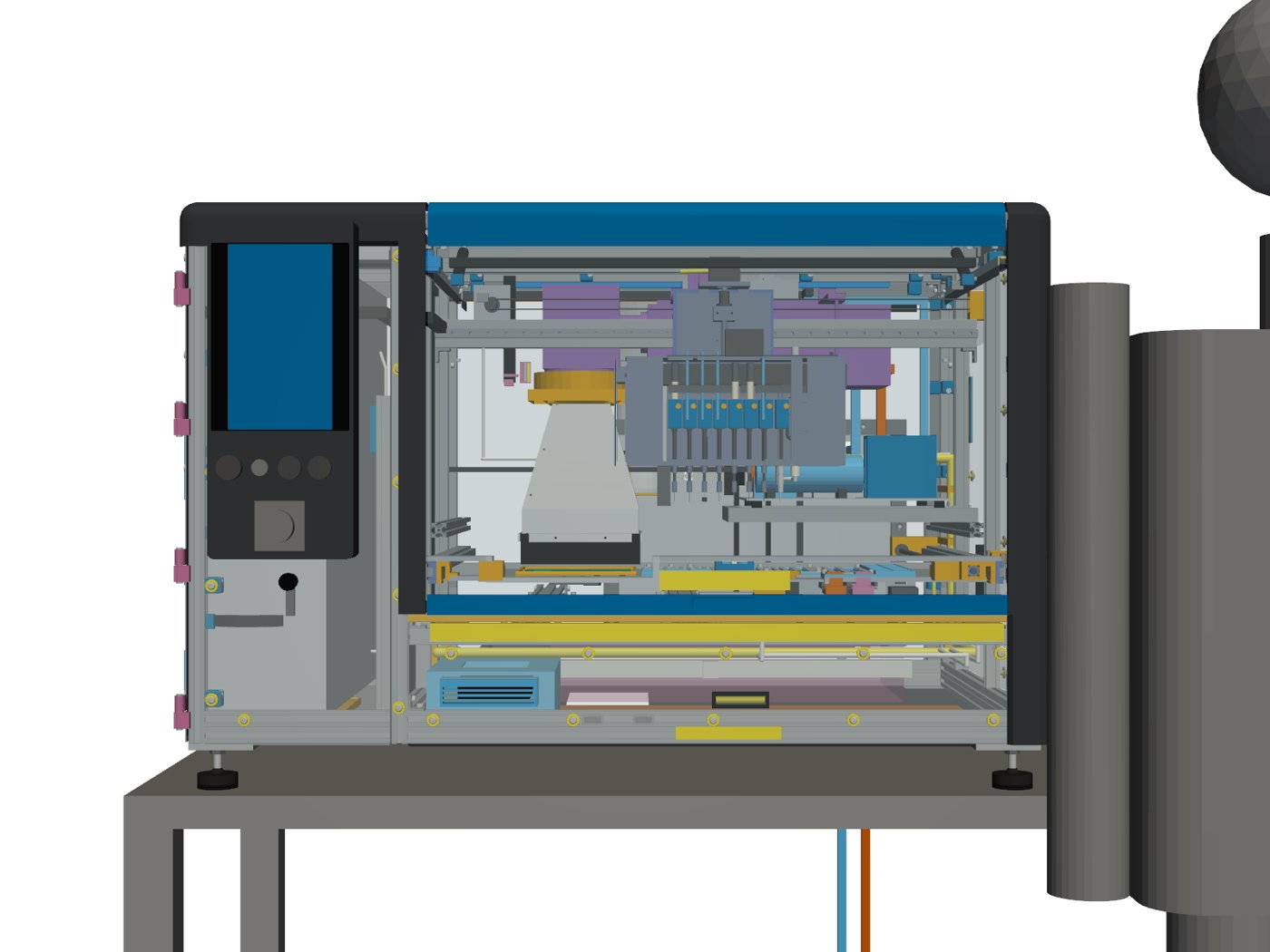
Run 41: carriage and gantry rotated 180 deg, cartridges still face the front
Run 41 (Nov 5, 2026). The X-carriage plates and the gantry finished the 180 degree rotation that run 40 started on the needle tray. Cartridge swaps still face the front.
Renders (run 41)
Downloads (run 41)
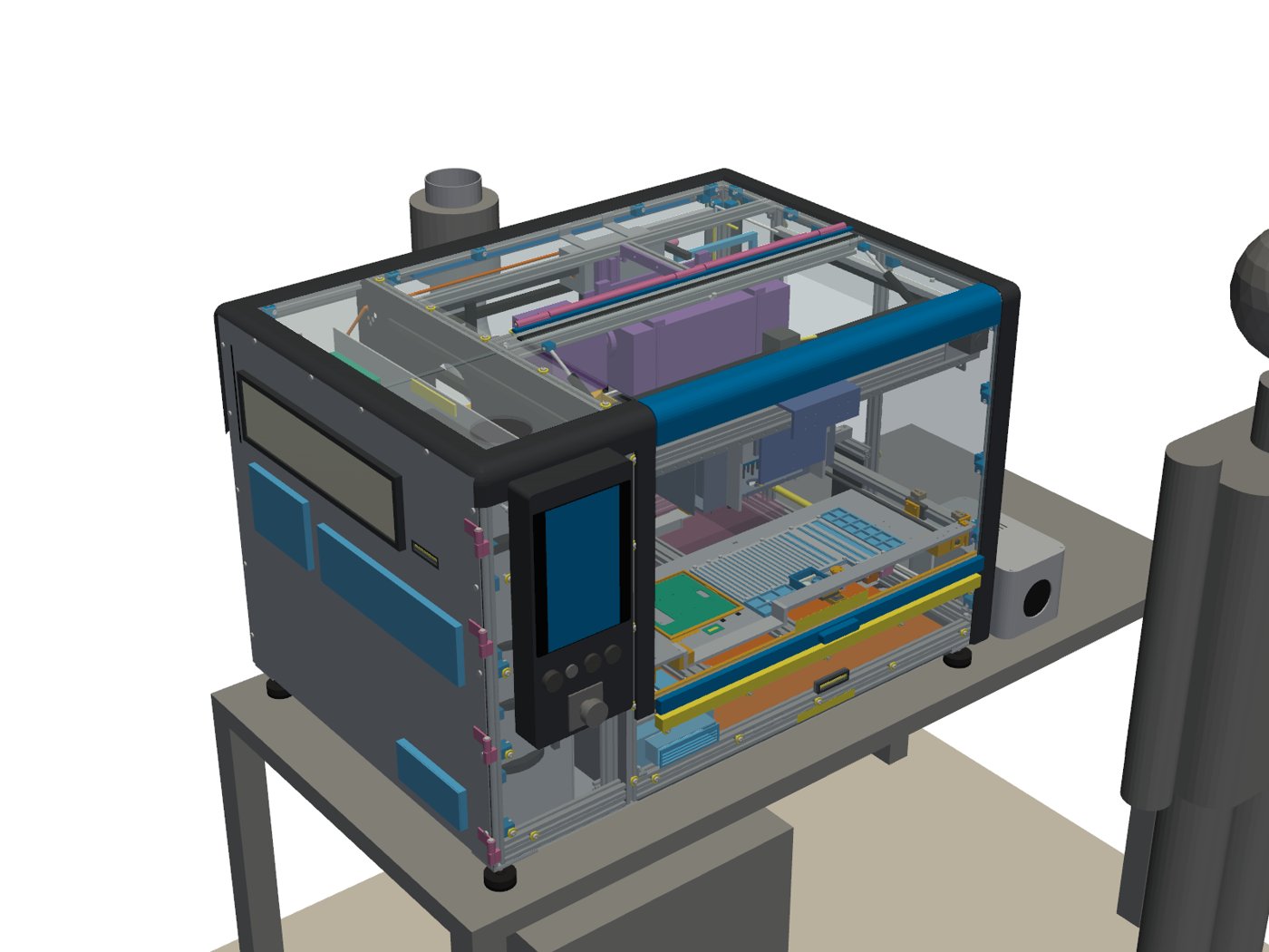
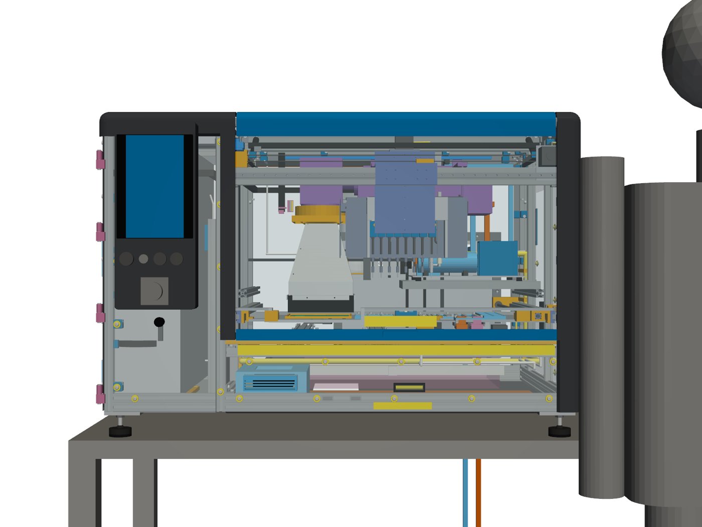
Run 40: needle tray rotated 180 deg, cartridges still face the front
Run 40 (Nov 5, 2026). The X-carriage needle tray is rotated 180 degrees so it faces the other way. Cartridge swaps still face the front. The PCB, the laser, the hood and the strip tray stay where run 39 put them.
Renders (run 40)
Downloads (run 40)
Run 39: needles reversed onto opposite seats, package 60 mm left, bigger strip tray
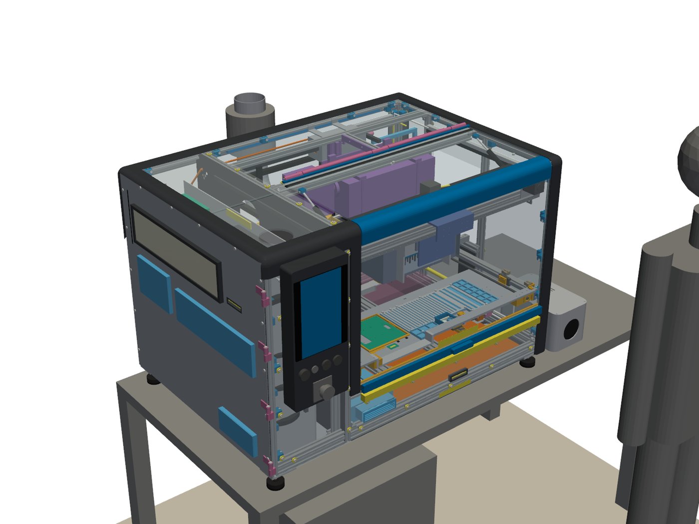
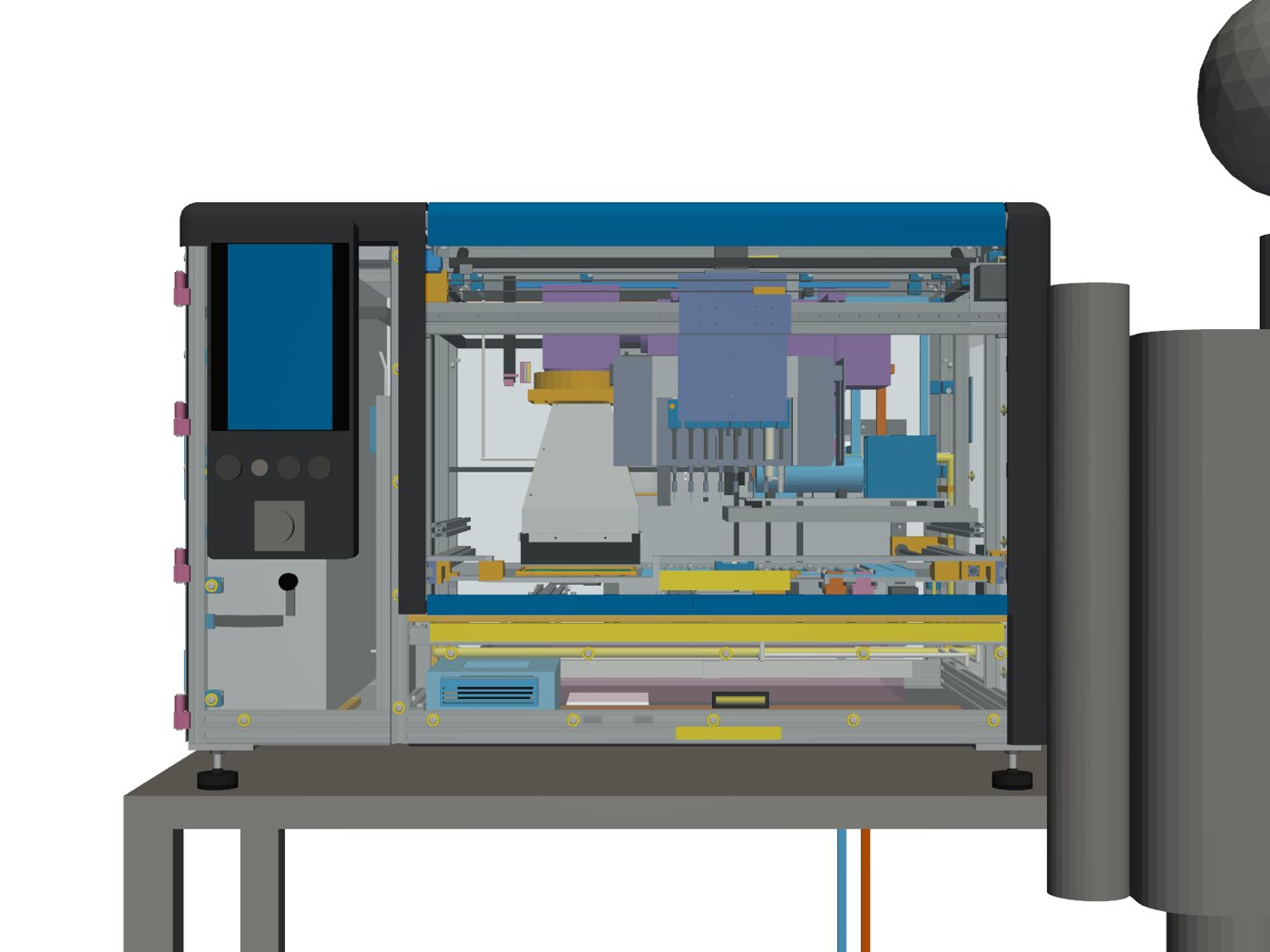
Run 39 (Nov 5, 2026). Each needle moved onto the opposite 20 mm seat. The PCB, the laser and the hood moved 60 mm to the left, and the freed space went to more strips and front pockets.
Renders (run 39)
Downloads (run 39)
Run 38: PCB and laser 30 mm to the left, bigger strip tray, fans outside the work area
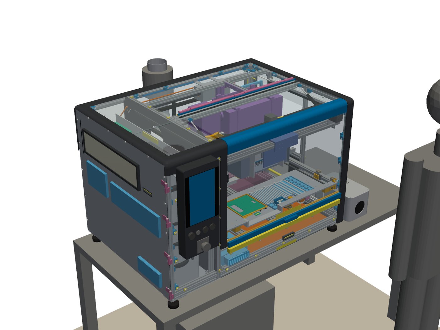
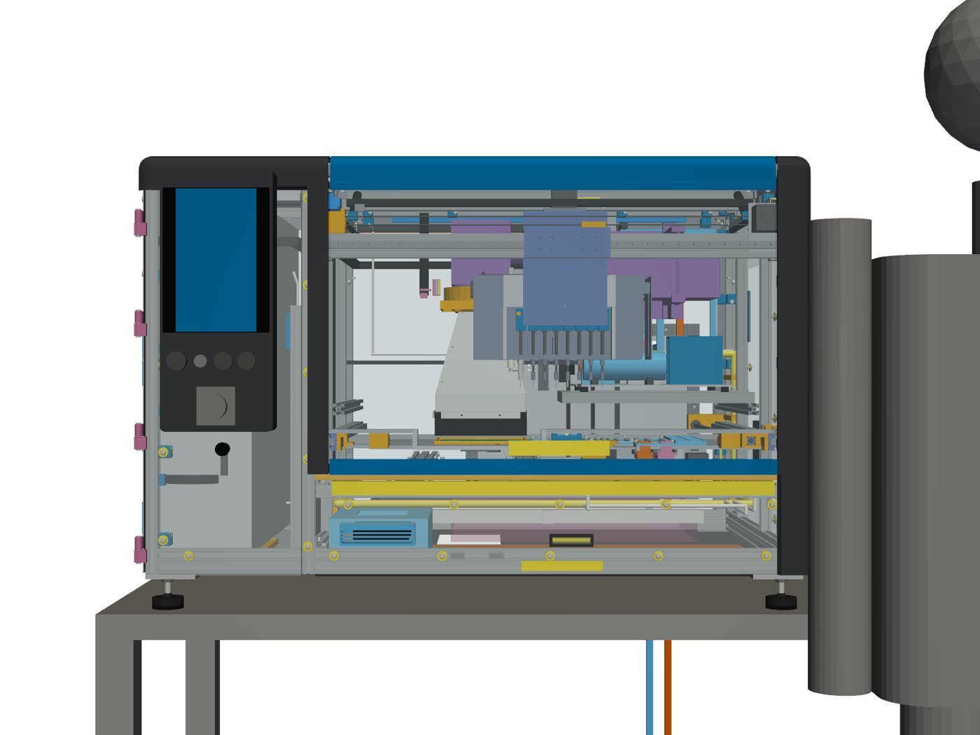
Run 38 (Nov 4, 2026). The PCB, the laser and the hood moved 30 mm to the left, the head travels 30 mm further left, and the freed space went to the strip tray. The cabinet fans sit on the electronics side of the left inner wall.
Renders (run 38)
Downloads (run 38)
Run 37: cut-tape strip rails, under-tray bins, turntable at the front
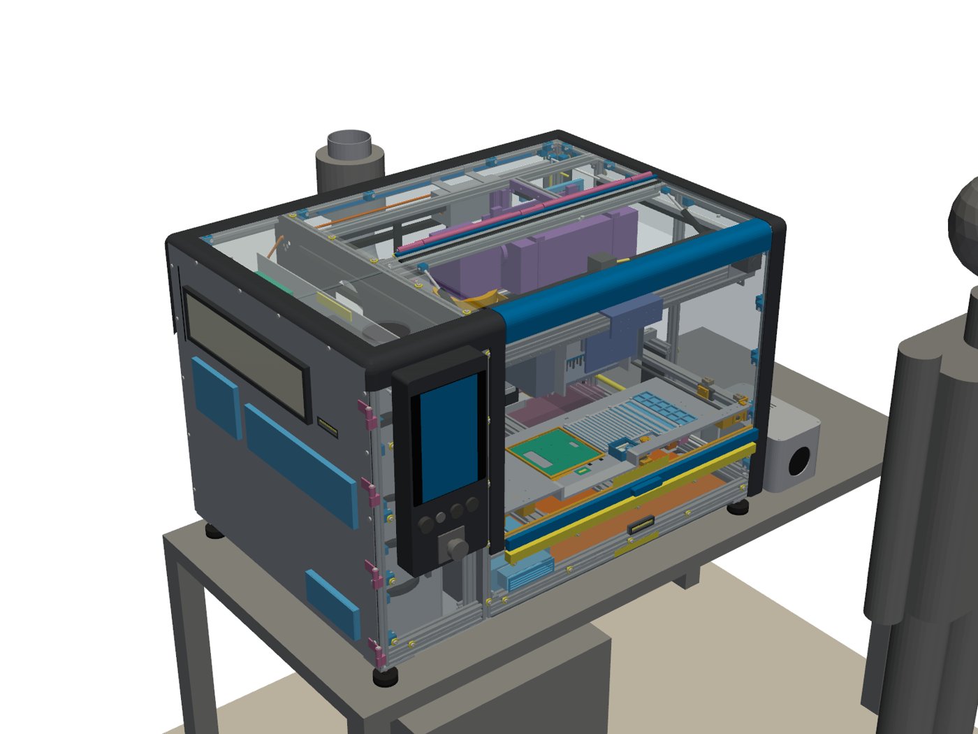
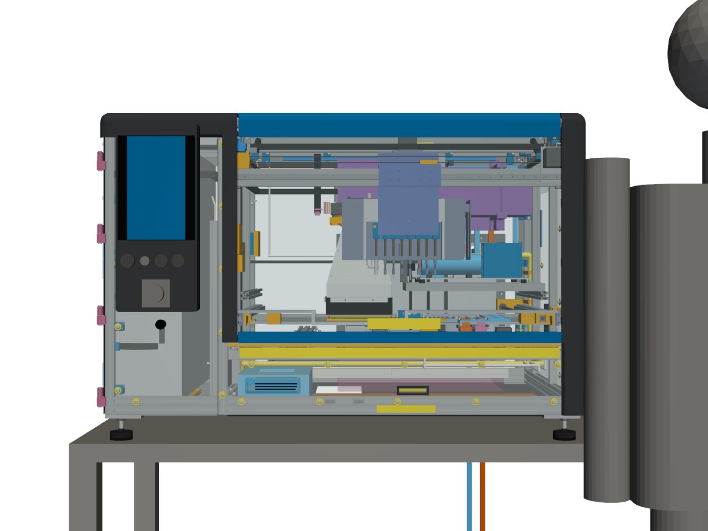
Run 37 (Nov 4, 2026). Cut-tape strips ran front to back in a strip-rail tray with 16 strips and 14 open pockets, and the turntable moved to the front.
Renders (run 37)
Downloads (run 37)
Run 35: needle remap, PCB at the rear, front maintenance pod
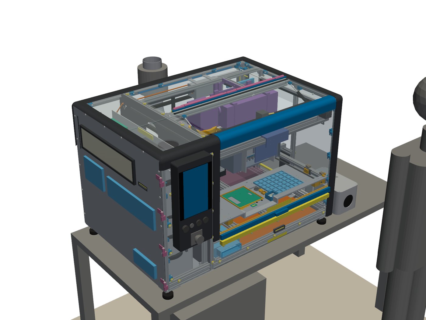
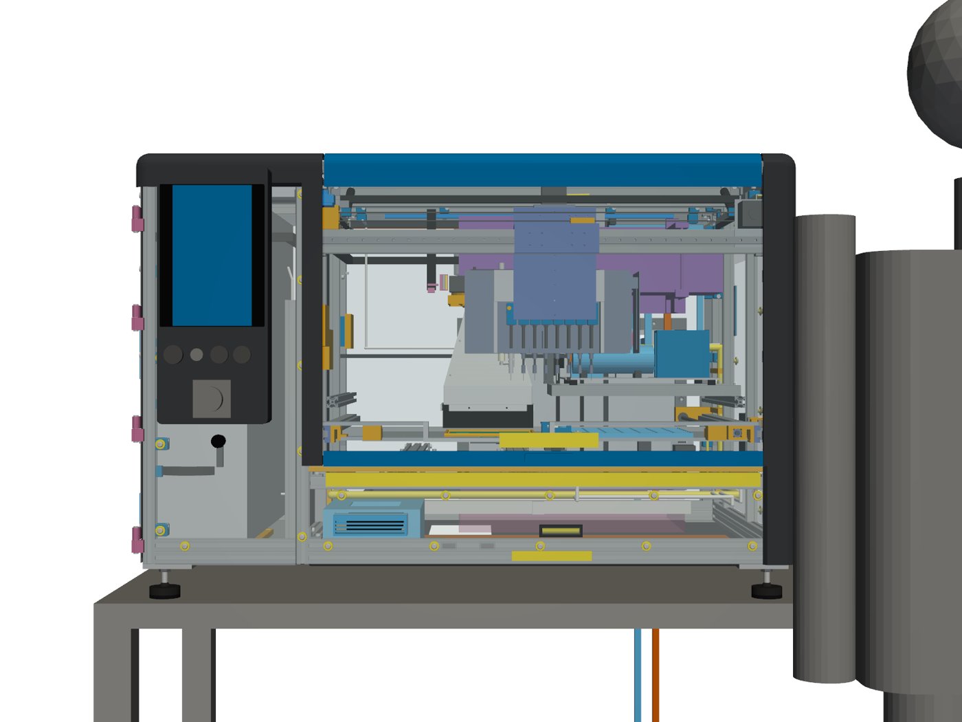
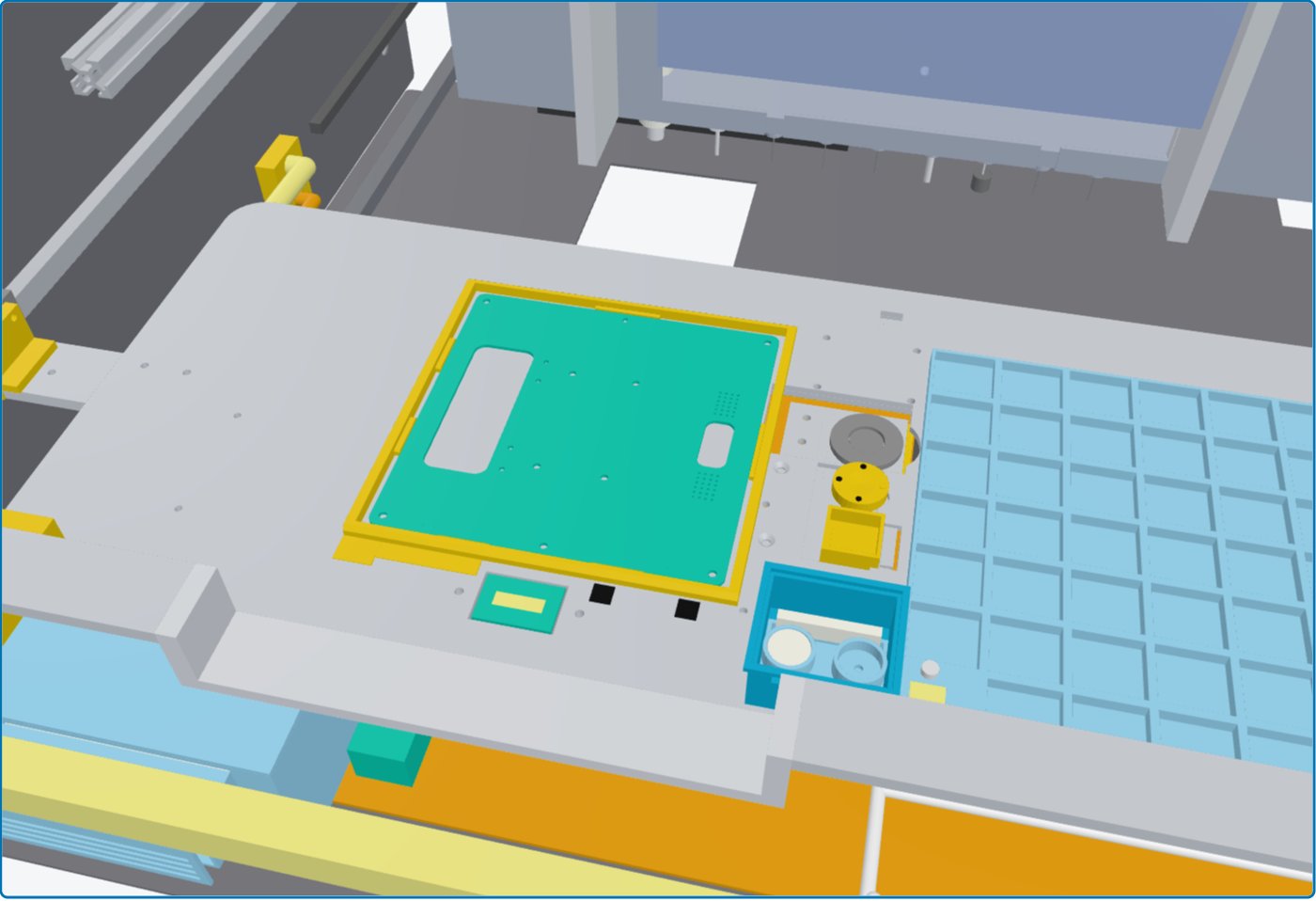
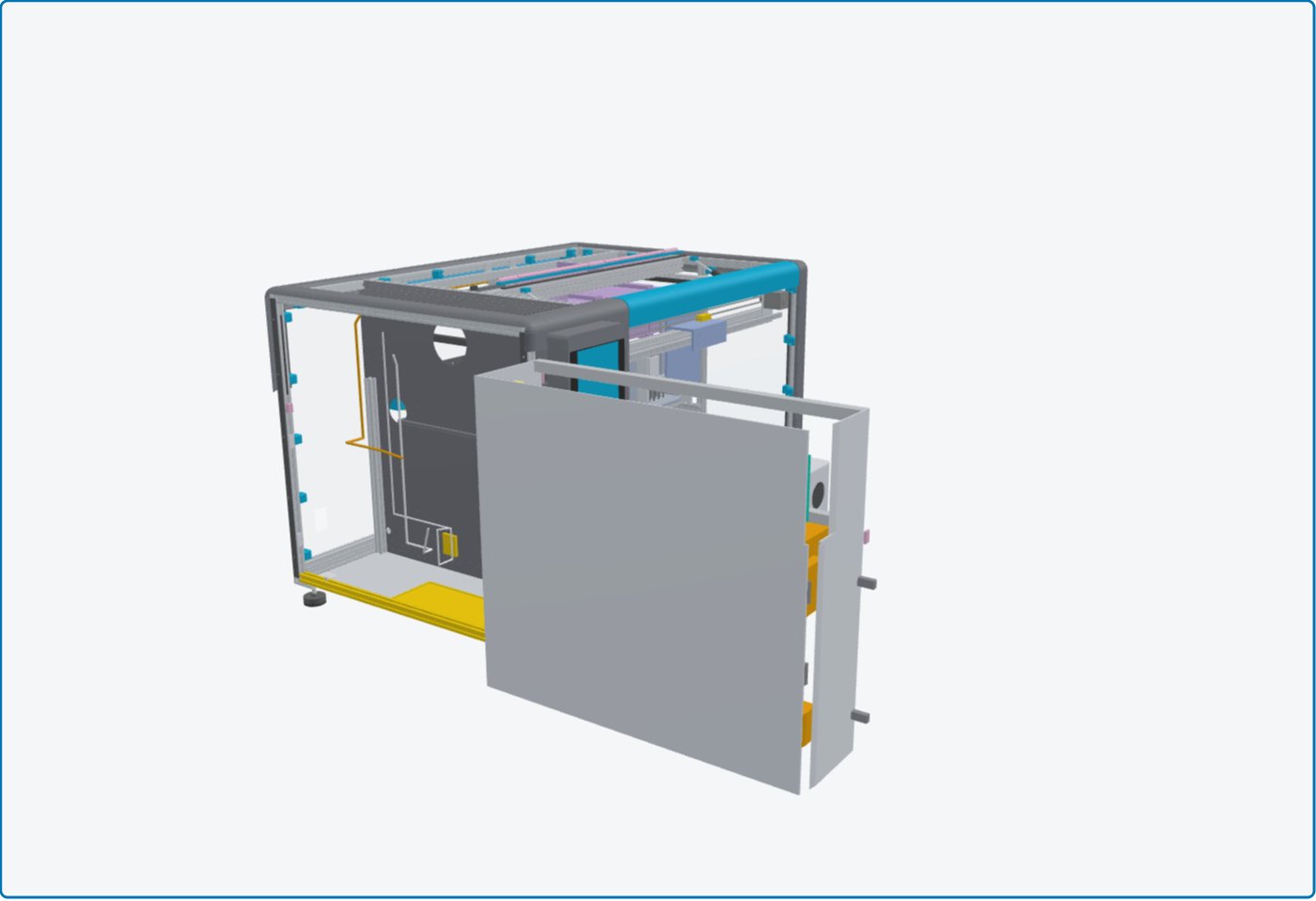
Run 35 (Nov 4, 2026). The pick needle N8 moved to the middle of the head, the PCB moved to the rear, and the needle sensor, a maintenance pod and a loading datum sat in front of the PCB.
Renders (run 35)
Downloads (run 35)
Run 34: bigger tray, carrier-mounted needle sensor, electronics door clearance
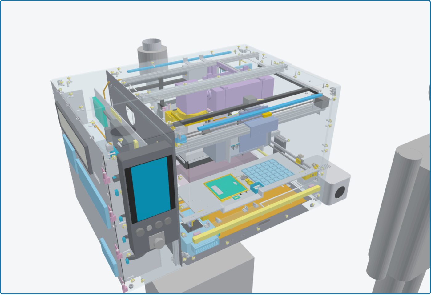
Run 34 (Nov 3, 2026). The tray carrier and the parts tray grew toward the rear, the needle sensor sat on a bracket on the carrier, the electronics door cleared the top edge trim, and the 3D model became Z up.
What was new in run 34
- Bigger tray. The laser-cut tray carrier is 68 mm longer toward the rear. At the rear end of its travel it still stays about 42 mm in front of the nearest fixed part behind it. The parts tray grew to 199 x 188.5 mm with a 7 x 7 grid (48 usable pockets, about 28.4 x 26.9 mm pitch, was 41). It stops at the line the needles can still reach, so N4, N5 and N8 reach every pocket. Tray travel limits are unchanged.
- Needle sensor on the carrier. The needle alignment sensor turned 180 degrees and moved onto the carrier top. Its 3D-printed bracket now sits flat on the carrier and is held by four M3 screws and nuts through both carrier plates, so it no longer sticks out on its own. Every needle can reach the sensor pads. The cable runs to the rear through a slot in the carrier.
- Electronics door clearance. The outer panel of the electronics door ran into the lower lip of the left top edge trim and the corner covers. The lip is now cut back over the panel, so the panel lifts off and the door swings clear. The earlier door sweep left the panel out because it is removed before the door opens; the sweeps now also check the panel coming off and the door swinging with the panel still on, against the trim.
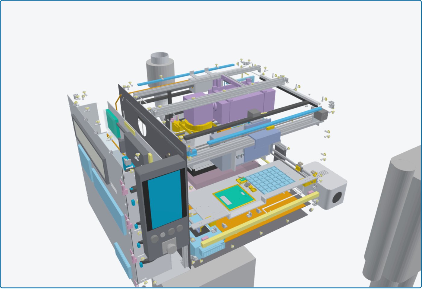
- Viewer. The model is now Z up, so orbit, views, section planes and explode follow the machine axes. The misc layer is one row and also holds the fasteners, frame corner brackets and bushings. The bench and the floor have their own rows and are hidden by default. The left and right column buttons were reworked and checked on the live site. The electronics door animation now takes the outer panel off first.
- Checks. The static interference check and all ten door, panel, tray and head sweeps report zero clashes. Needle reach, sensor reach and an automatic attachment check of every animation were run.
Renders (run 34)
Downloads (run 34)
Run 33: MiniPC assembly, needle-only air, 200 mm cam slide
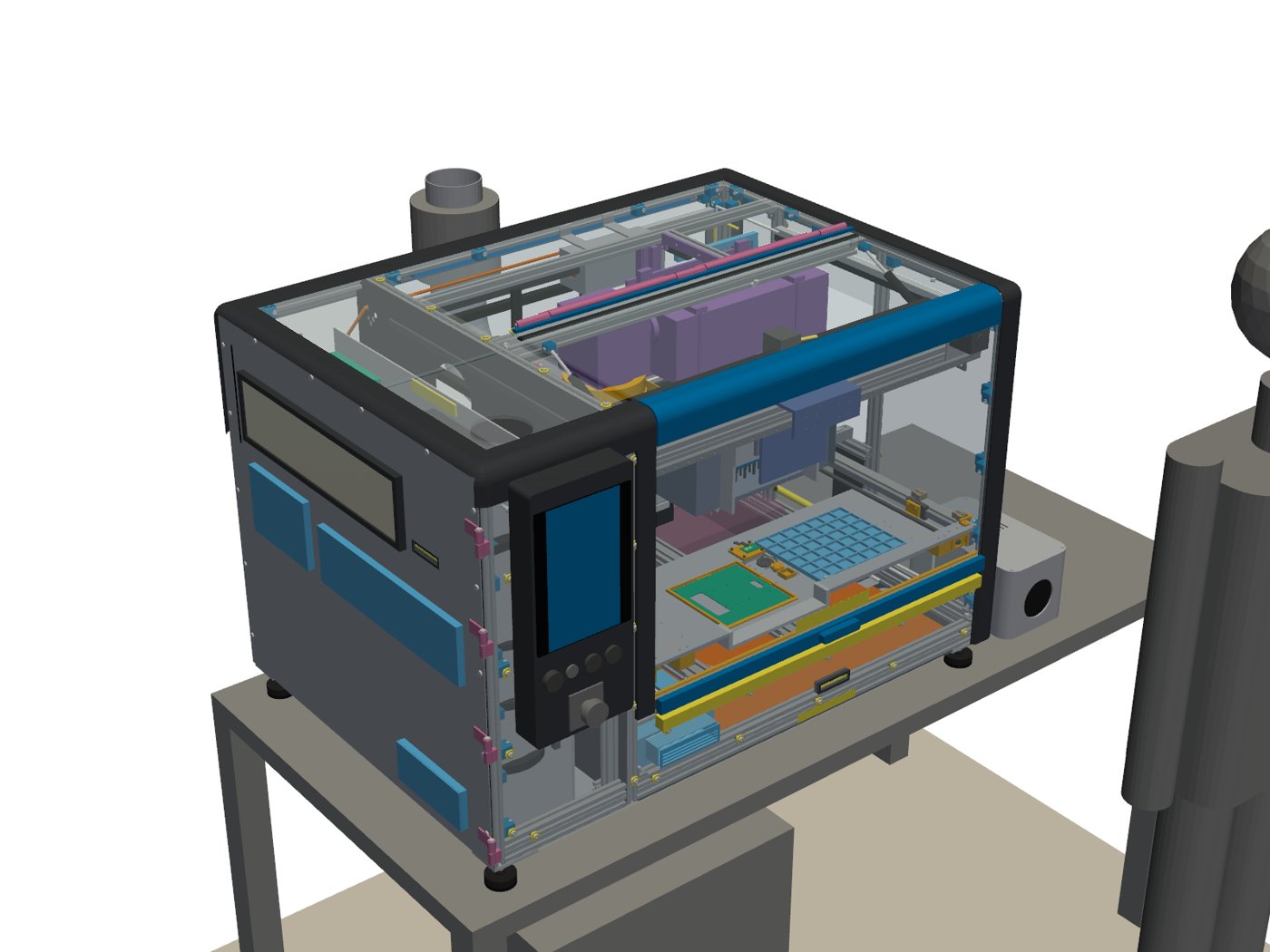
Run 33 (Nov 3, 2026). The MiniPC is its own assembly beside the machine, the air system now serves only the needles, the cam slide has a 200 mm stroke, and the 3D viewer has a new layout.
What was new in run 33
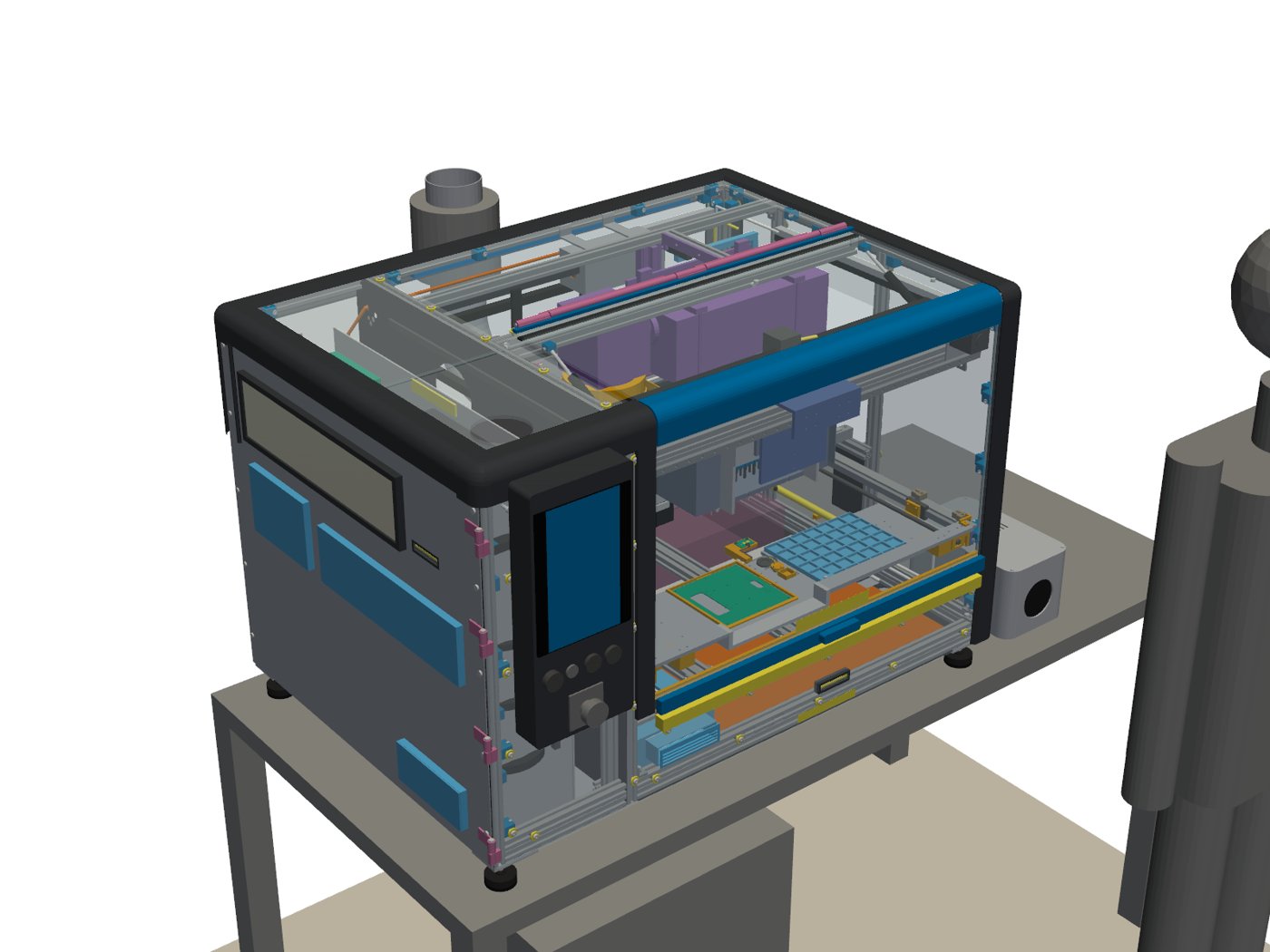
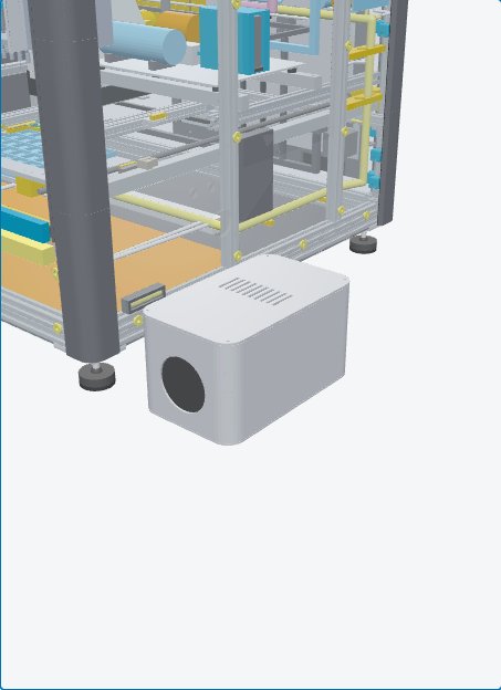
- MiniPC as its own assembly. The MiniPC enclosure and everything inside it form a separate top-level assembly, "MiniPC", next to "OSSO Machine" in the STEP, the GLB and the viewer. It stands on the bench 60 mm to the right of the machine, clear of the gull-wing door, the electronics door and every other moving part.
- Air for the needles only. The air system now feeds only N4, N5 and N8 (vacuum pick and blow-off), the N1 puff and N7 (hot air or air clean). The last hoses from the old cylinder supply are gone. The pressure tank shrank from 225 to 100 mL and the valve block from seven valves to five. The 24 V pump was rechecked: with targets of -60 kPa and 0.6 bar it stays inside its continuous-duty rating and still gives more than twice the N7 flow. The 1.0 bar relief valve stays as a guard.
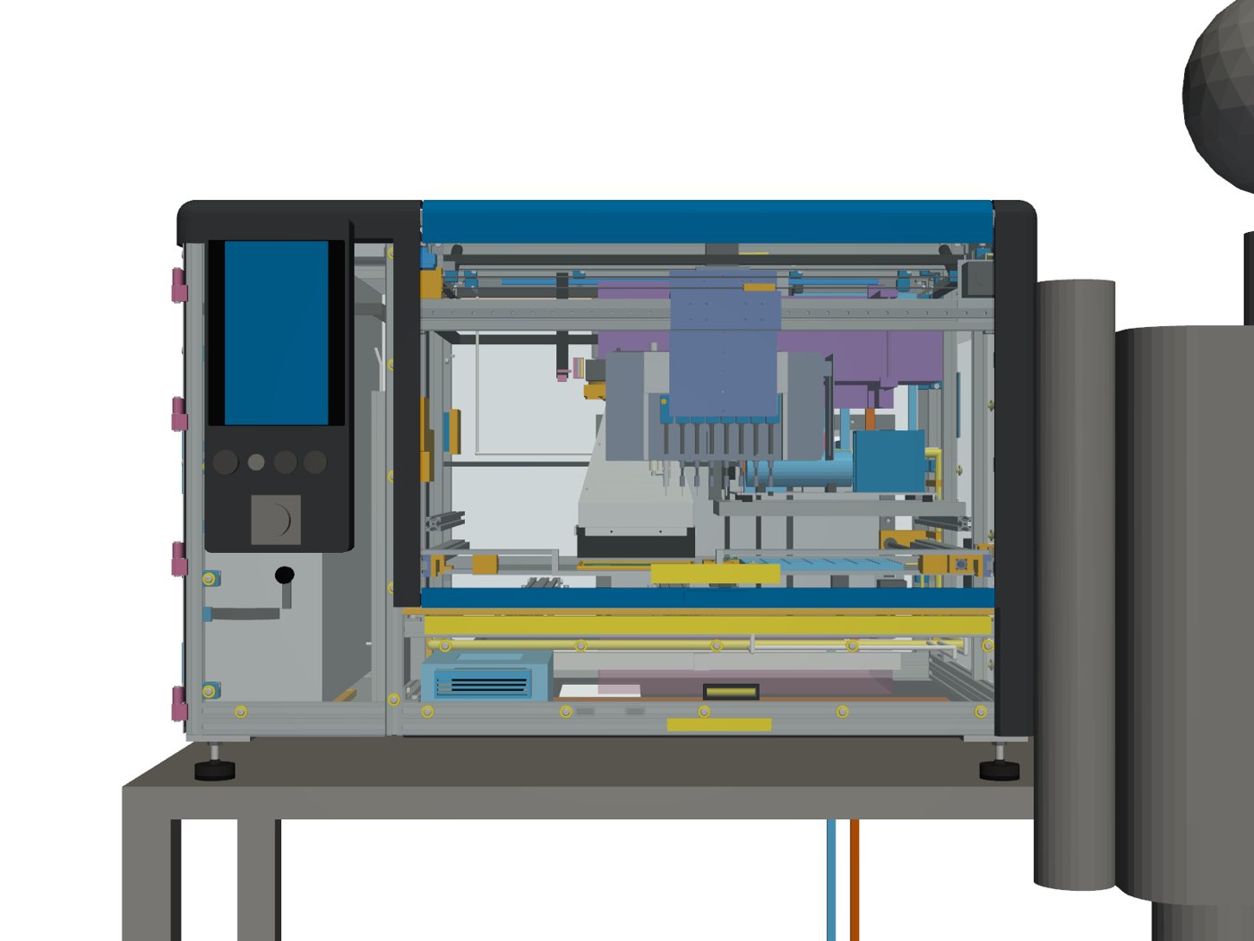
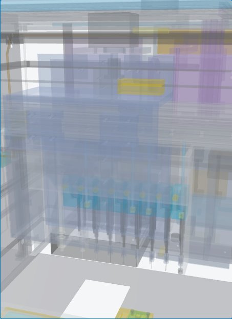
- 200 mm stroke cam slide. The cam slide is now the 200 mm stroke version, so the full 170 mm cam stroke fits with room to spare. The longer body passes through a slot in the left head panel, the motor end moved 15 mm right, and one electronics door fan sits 40 mm lower to clear it. The eight-needle head layout is unchanged.
- Viewer. Parts are in a collapsible column on the left and all controls are in a collapsible column on the right. The selected part's info shows under the model and leaves out blank rows; click the part again to deselect it. The explode slider reaches much further and also spreads the parts inside each group, to get at interior parts. The scale figure, helpers, chiller and its lines, and fasteners are one hidden "misc" group that Show all and Isolate leave out.
- Checks. The static interference check and all eight door, tray and head sweeps report zero clashes. Cam reach, tip-over, mass and an automatic attachment check of every animation were run.
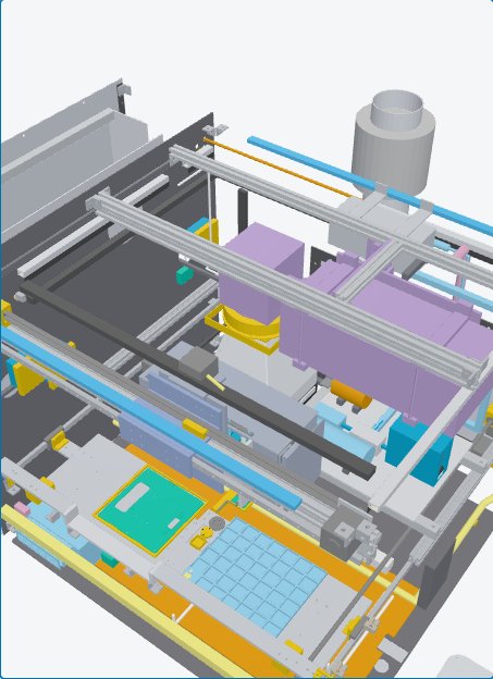
Renders (run 33)
Downloads (run 33)
Run 32: fixed hood, bigger tray
Run 32 (Nov 3, 2026). The PCB holder moved as far left as the needles allow, the tray grew into the freed space, and the laser hood is now fixed: no cylinders, just a soft silicone band that wipes the board.
What was new in run 32
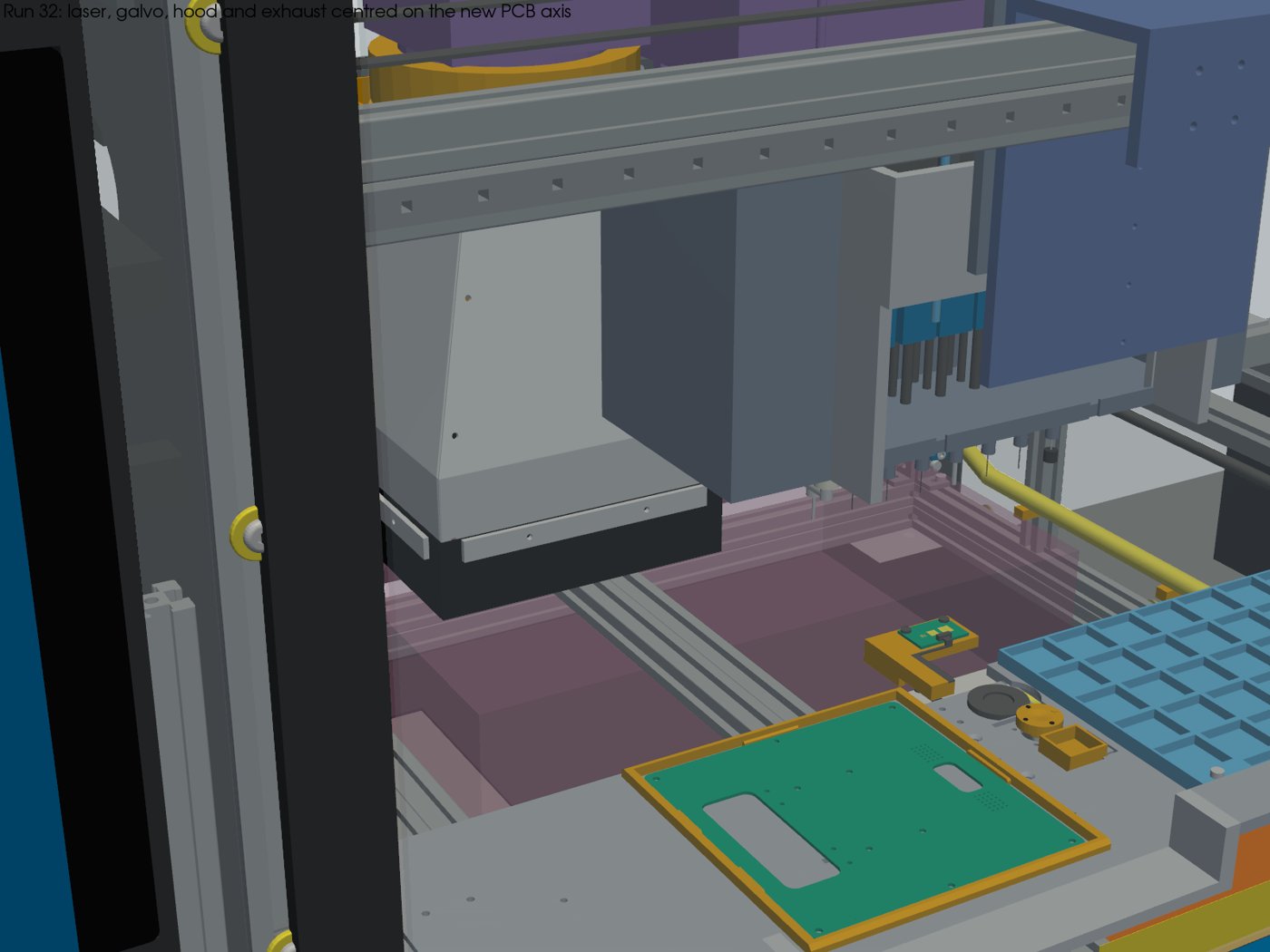
- PCB further left. The PCB pocket, turntable and up camera moved 7 mm left, the most that still lets needles N1 to N7 reach the whole board. The laser, galvo, hood and exhaust moved with it, so the laser stays centered on the board.
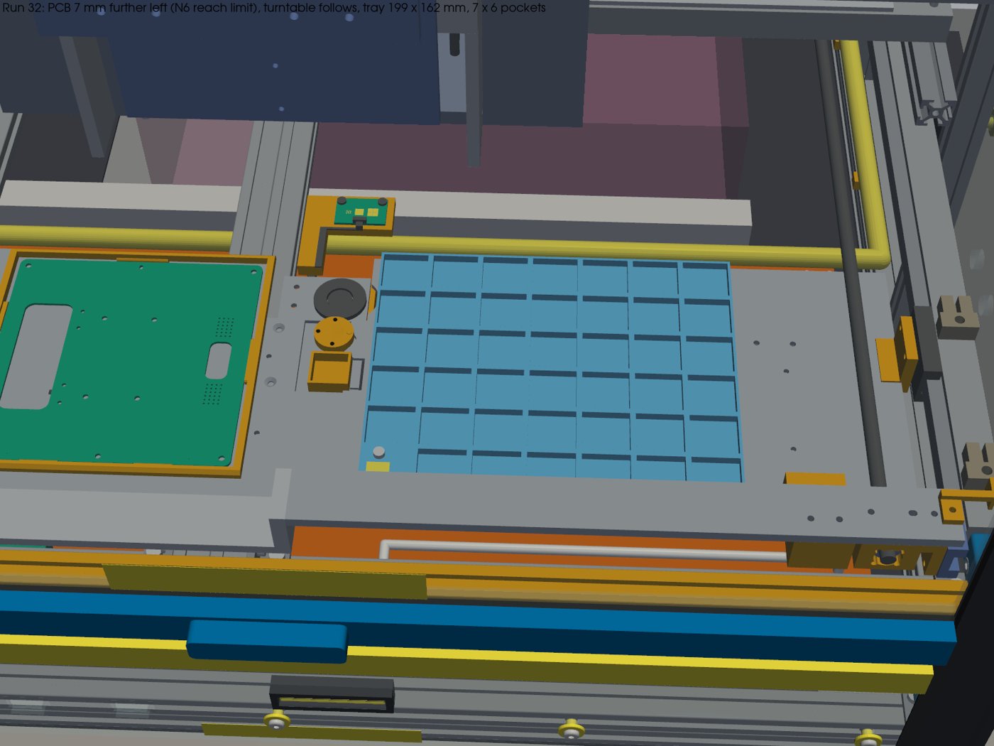
- Bigger tray. One 199 x 162 mm tray with a 7 x 6 grid (41 usable pockets, about 28 x 27 mm pitch). The N4 pick nozzle and the N5 and N8 tools reach every pocket.
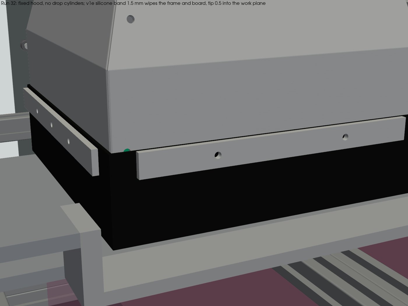
- Fixed laser hood. The two hood-drop cylinders, their valve and hoses are gone. The hood height is set once with two manual jack screws after focusing. A soft black silicone band (1.5 mm, 50 to 60 Shore A) sits 0.5 mm into the board surface and wipes over it as the tray comes in; the leading edges of the pocket frame are chamfered so nothing snags. The hood-in-place sensor stays in the laser enable chain.
- Tray bridge. The front bridge of the tray dips under the silicone band where it passes the hood.
- Viewer. Fasteners are now in their own hidden layer with a separate toggle. Show all and isolate leave them out.
- Animations. Six clips: the door now swings on its real hinge with both gas struts pivoting on their ball studs, the electronics door stops at its 90 and 180 degree detents, tray picks show the cam stroke and the head Z drop, the turntable indexes on its rack, and the gantry clip includes Z.
- Checks. Static interference plus door, electronics door, tray, head X and head Z sweeps report zero clashes outside the designed band wipe. Tip-over and an automatic attachment check of every animation were run.
Animations (run 32)
The run 32 animations play inside the 3D viewer, each from its own saved view:
- Gantry and head moves (X, Y, Z)
- Needle actions (N7 to N8)
- Turntable index (rack + detent, 2 x 90 deg)
- Tray picks (N4: cam, Z drop, pick, place on the PCB)
- Gull-wing door (hinge + gas struts)
- Electronics door swing (detents 90 / 180)
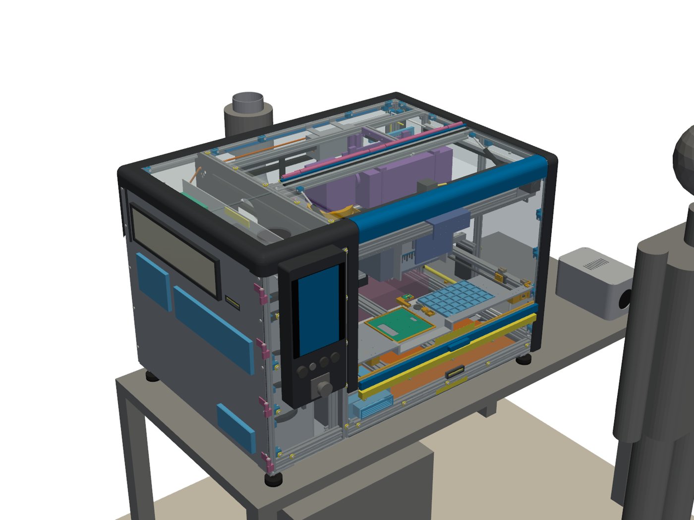
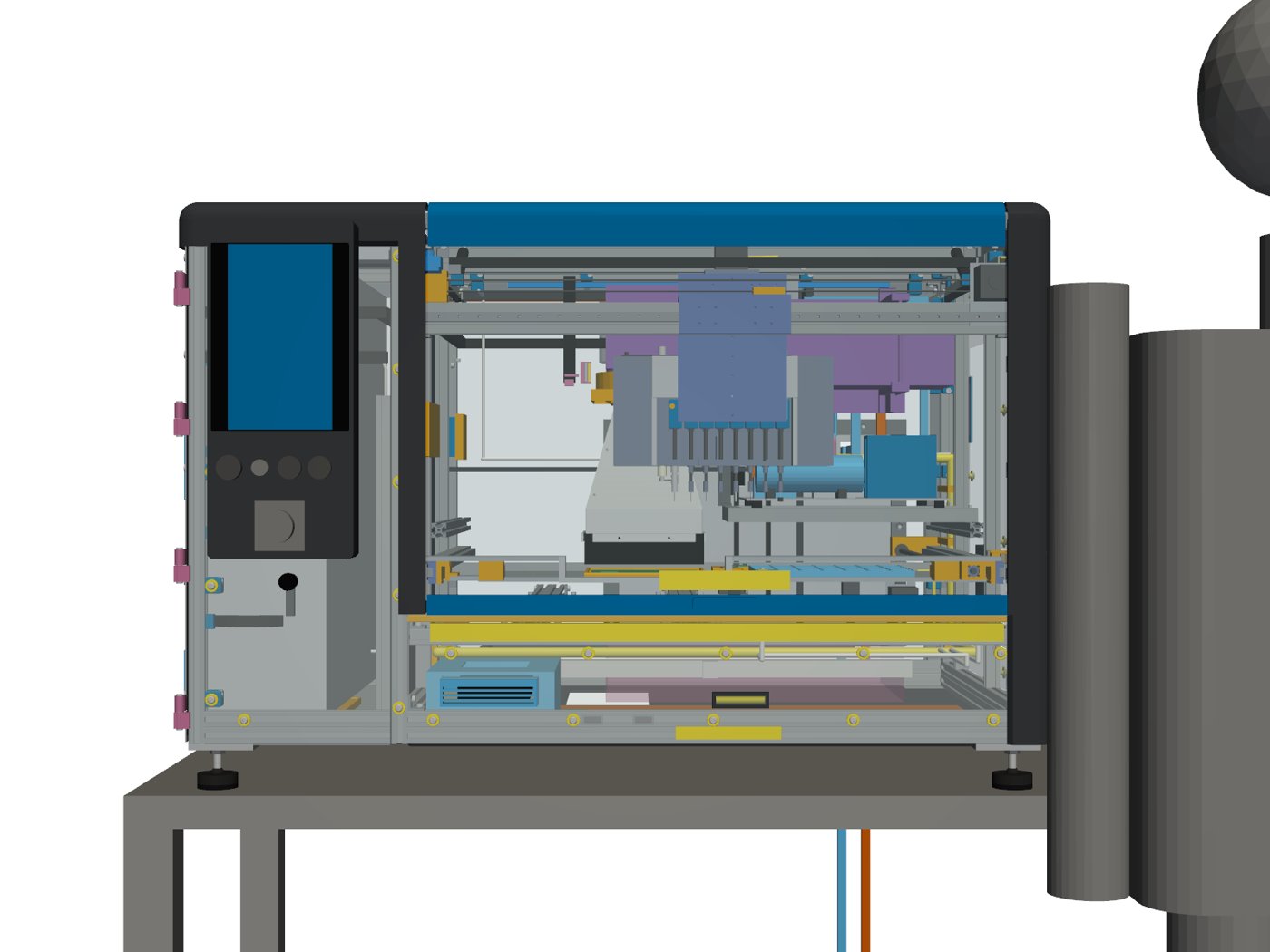
Renders (run 32)
Downloads (run 32)
Run 31: eight needles, one tray
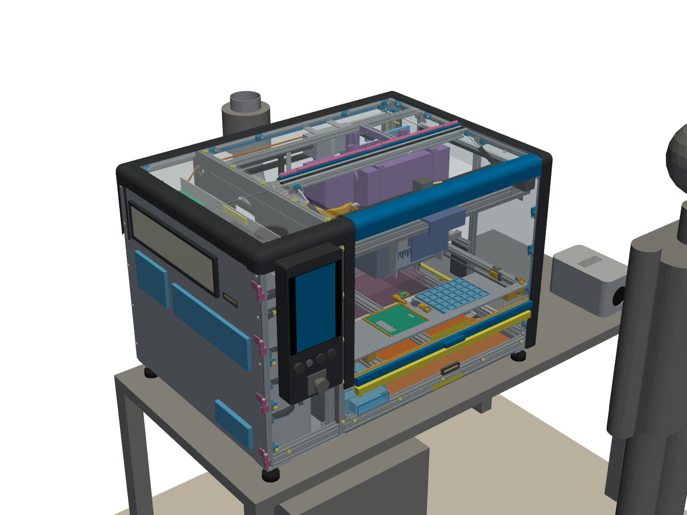
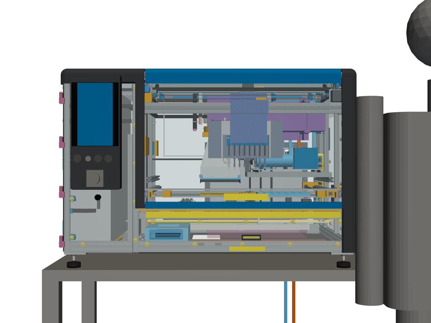
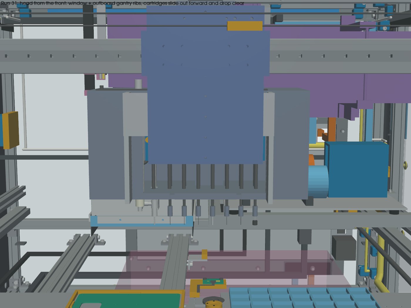
Run 31 (Nov 3, 2026). The head carries eight tools at 20 mm pitch, the PCB sits at the far left with a single tray on the right, and a new compact pump supplies vacuum and air.
What's new in run 31
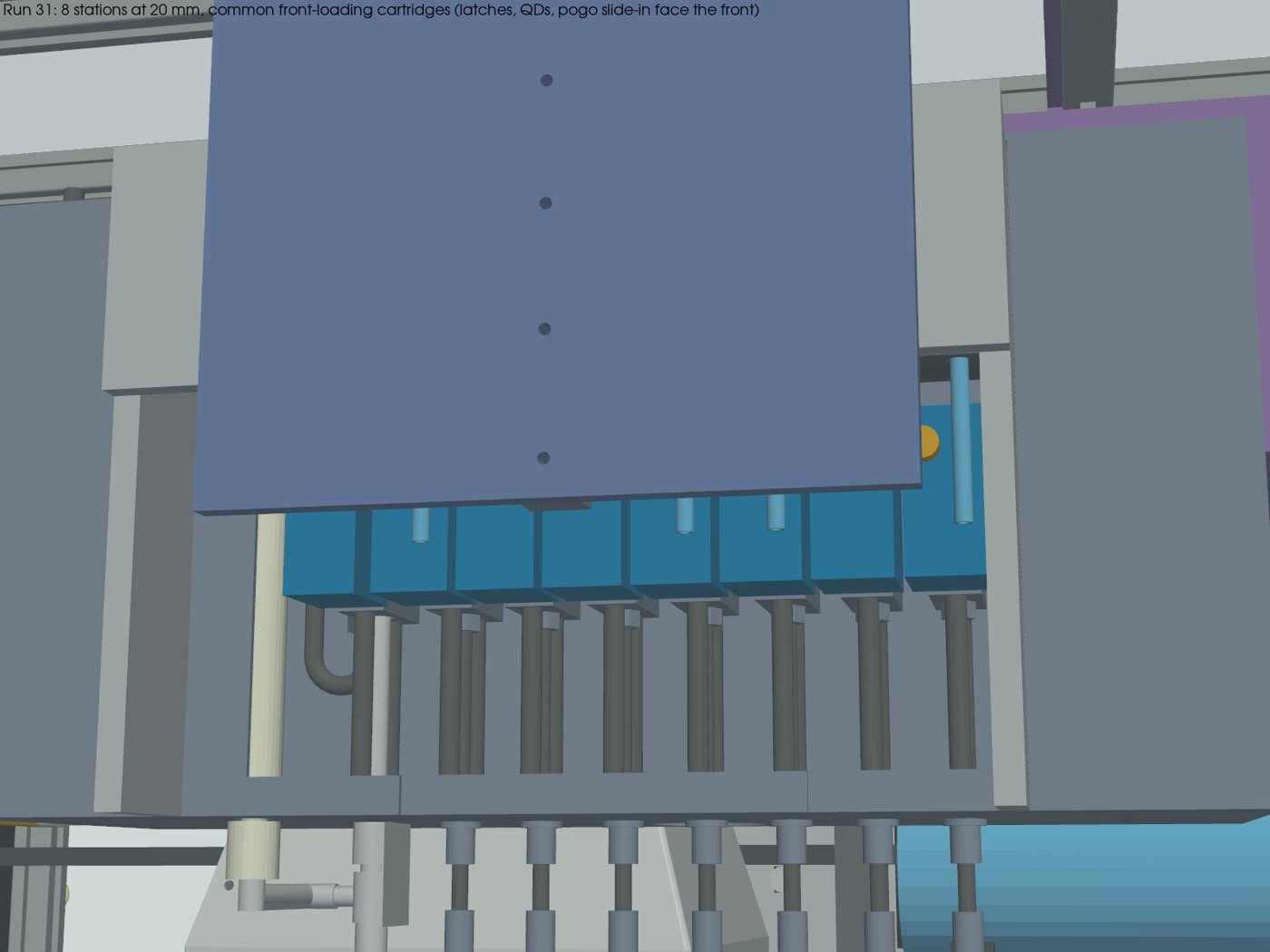
- Eight stations. N1 balls, N2 flux, N3 IPA, N4 Juki 505 pick nozzle (2.5 mm OD / 1.3 mm ID), N5 0402 needle (25 ga), N6 paste, N7 hot air with air clean, N8 a fixed 6 to 8 mm soft cup for companion boards (50 g max).
- Own steppers. N1, N2, N3 and N6 each get a separate 10 mm stepper for dosing.
- One cartridge for all. Each syringe sits in a common cartridge; the dovetail, latch, spring contacts and quick-disconnect all face the front, so a swap needs no tools.
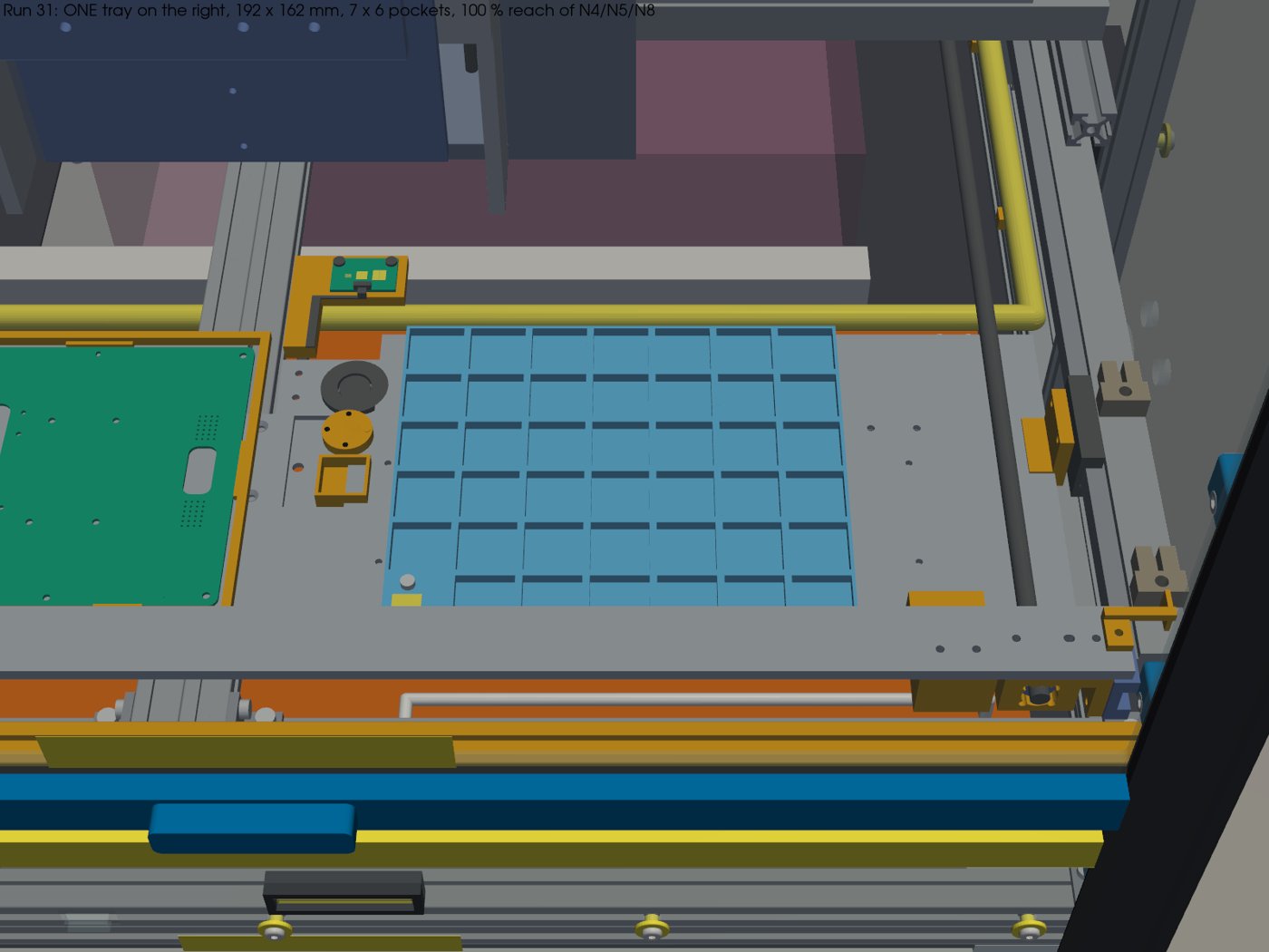
- PCB left, one tray right. A 192 x 162 mm tray with a 7 x 6 grid (42 pockets) replaces the two trays.
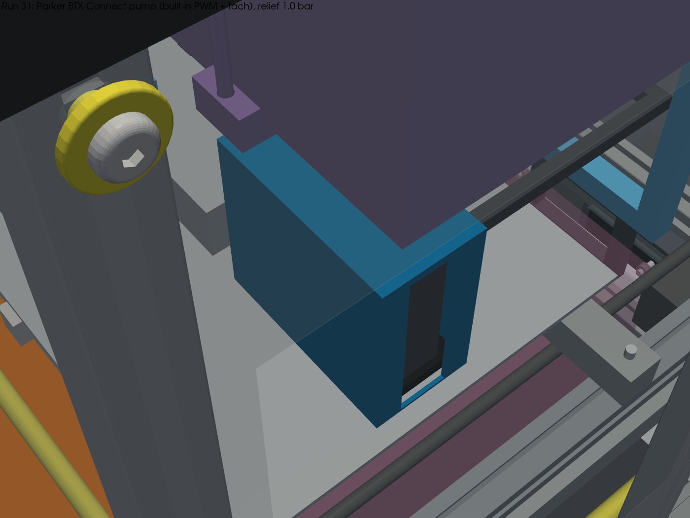
- New pump. A 24 V diaphragm pump at -70 kPa / 1.0 bar with a 1.0 bar relief valve; a relay keeps it hard-off when idle.
- Checks. A full interference check of every part, plus all door, tray, hood and head sweeps and the cartridge swap path, now reports zero clashes. Tip-over and spring sizing were redone.
Renders (run 31)
Downloads (run 31)
- osso_top_run31.step (zip)
- osso_top_run31.glb (zip)
- osso_top_run31.usdz (zip)
- Software rules SR-001 to SR-054
Run 30: one rear service panel
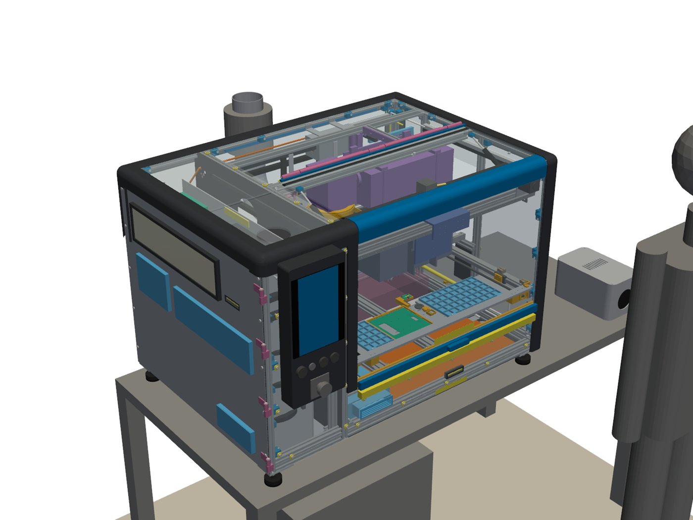
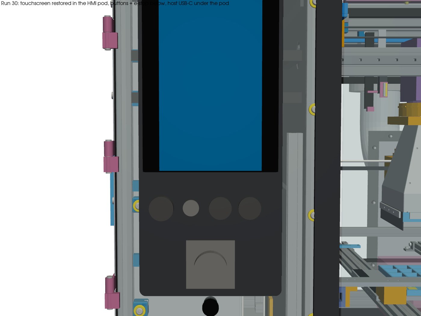
Run 30 (Nov 2, 2026). Every outside connection now goes through one panel at the back, the pick needles with vacuum can reach every tray cell, and the touchscreen is back in the front pod.
What's new in run 30
- Vacuum where it reaches. Vacuum moved to needles N1 and N6. N1 reaches all of tray L and the PCB, N6 all of tray R and the PCB, so every tray cell can be picked again.
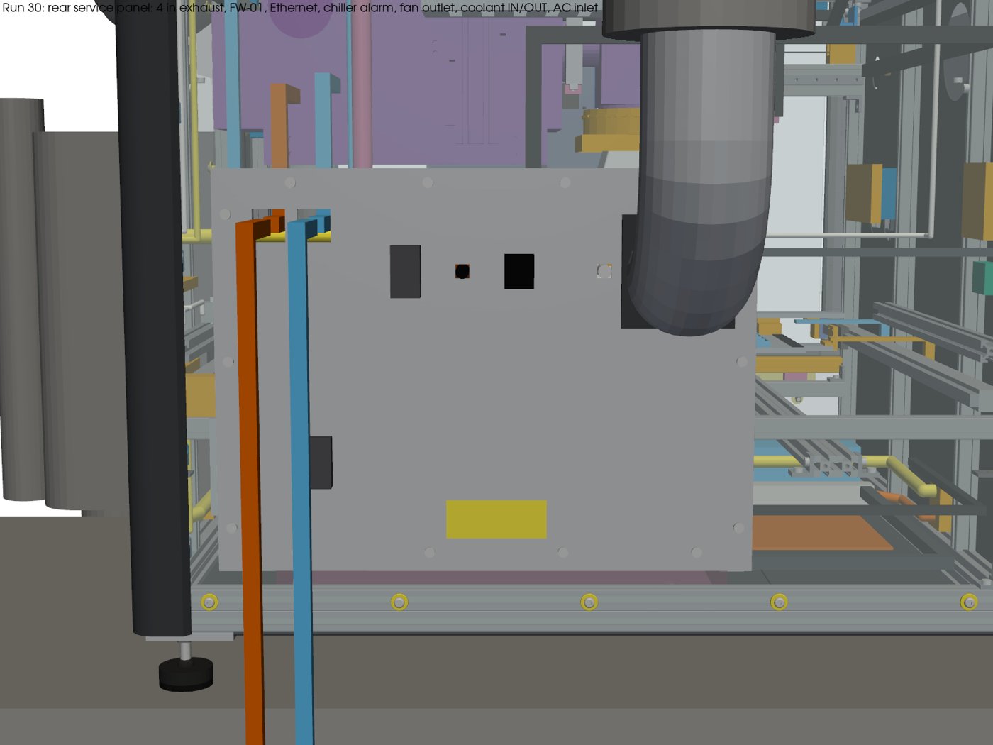
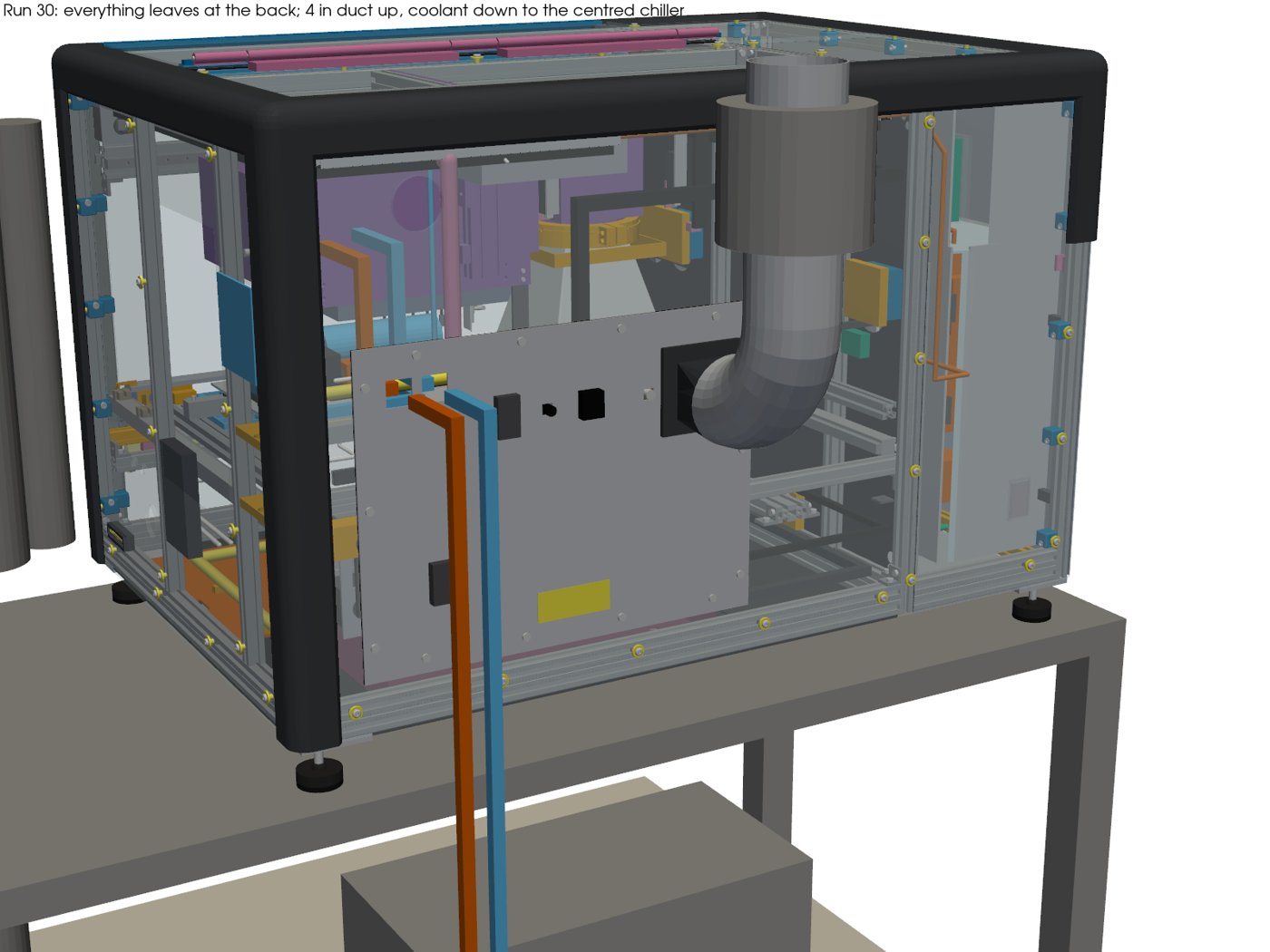
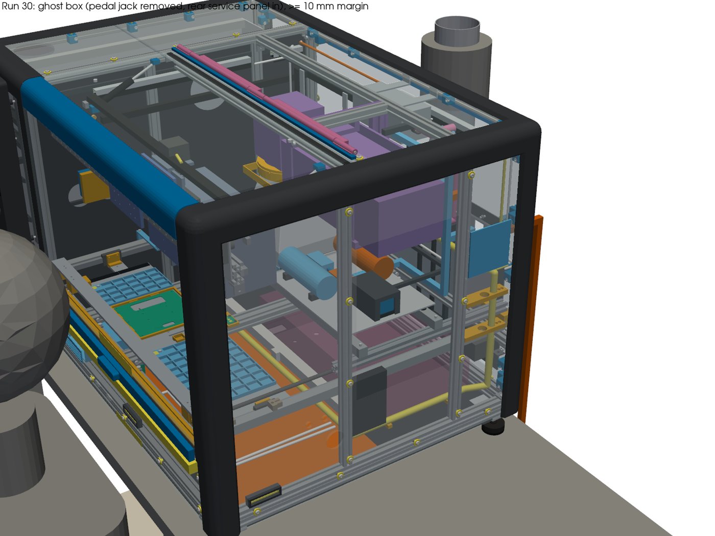
- One rear service panel. AC power in, coolant in and out, Ethernet, the chiller alarm, the fume-fan outlet, the airflow switch and the exhaust all leave through one panel on the back. The only front connection is the host USB-C under the control panel.
- Standard 4 in exhaust. The fume duct leaves the back through a square-to-round transition into a 4 in round duct with a short upward segment.
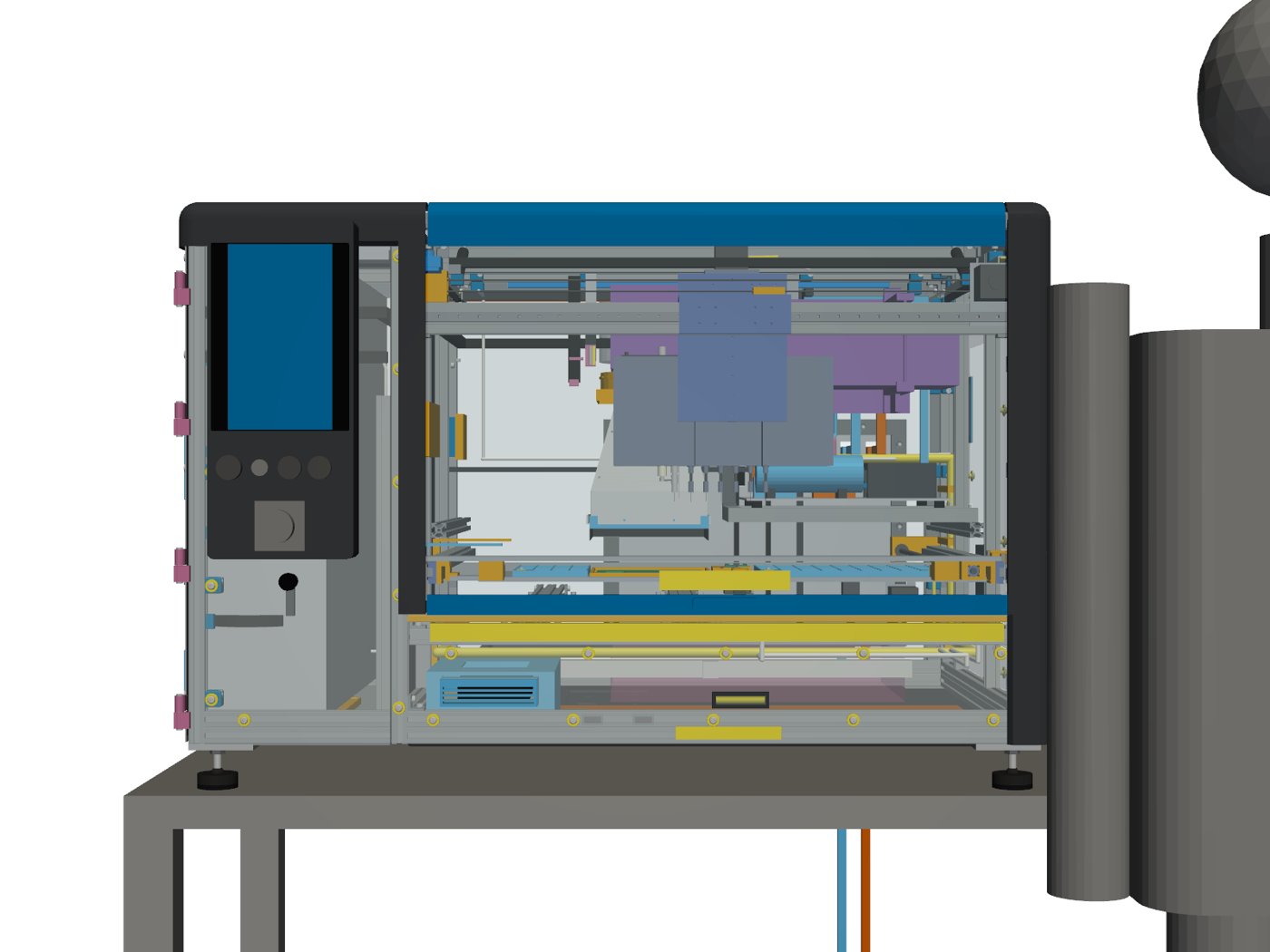
- Touchscreen restored. The 10.1 in touchscreen is back in the front HMI pod, above the buttons and the e-stop.
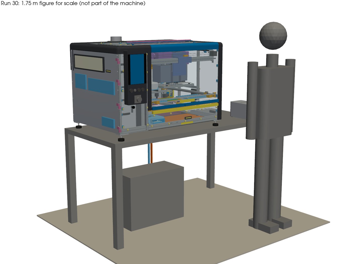
- Chiller under the machine. The chiller sits centred on the floor under the bench, with its hoses coming down from the rear panel.
- No foot pedal. START and HOLD are on the front pod and the touchscreen only.
- Scale. A plain 1.75 m figure stands next to the machine in the renders (not part of the machine).
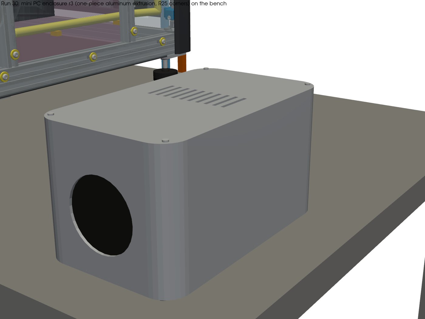
- Example enclosure r3. The example mini PC enclosure is now one continuous aluminum extrusion with generous rounded corners.
- Checks. Every moving part was swept again, the tip-over check and the free-space box were redone, and the routing bend radii were checked.
Animation (run 30)
Renders (run 30)
Downloads (run 30)
- osso_top_run30.step (zip)
- osso_top_run30.glb (zip)
- osso_top_run30.usdz (zip)
- Example mini PC enclosure r3 (STEP)
- Example enclosure r3 drawing (PDF)
- Software rules SR-001 to SR-051
Runs 27 to 29 were internal steps between run 26 and run 30.
Run 26: bigger trays, everything inside
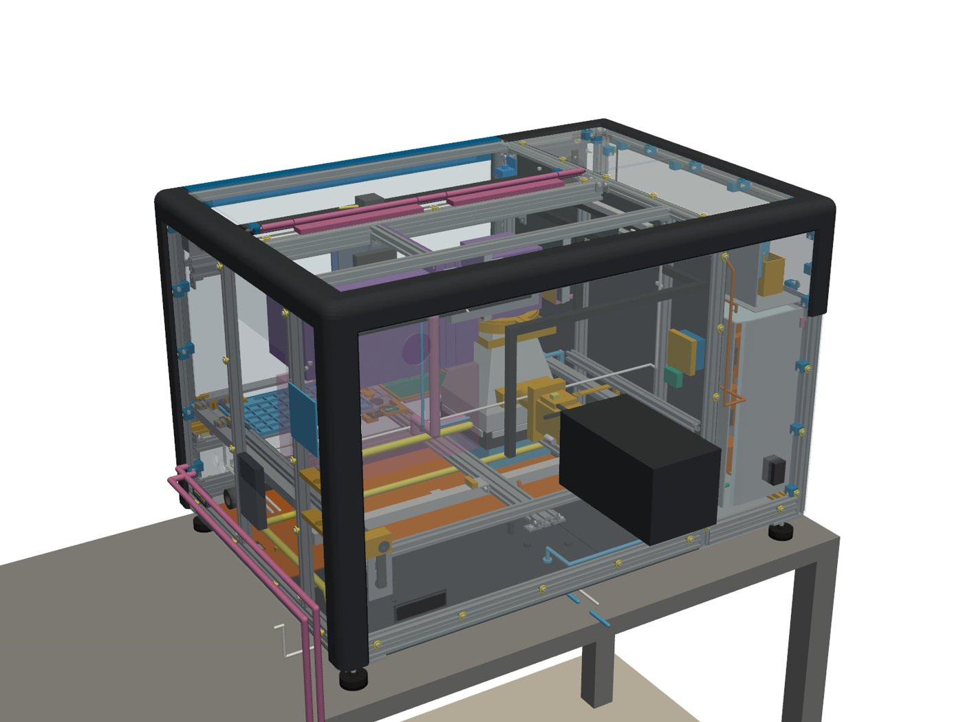
Run 26 (Nov 2, 2026). The part trays grow to fill each side of the PCB pocket, and the air filter unit and the optional lube pump move inside the enclosure.
What's new in run 26
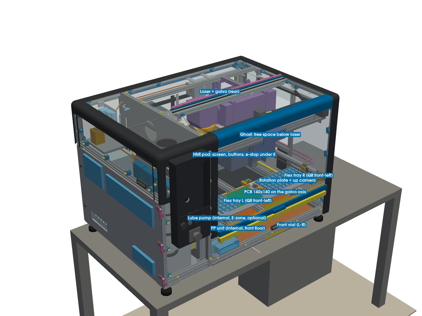
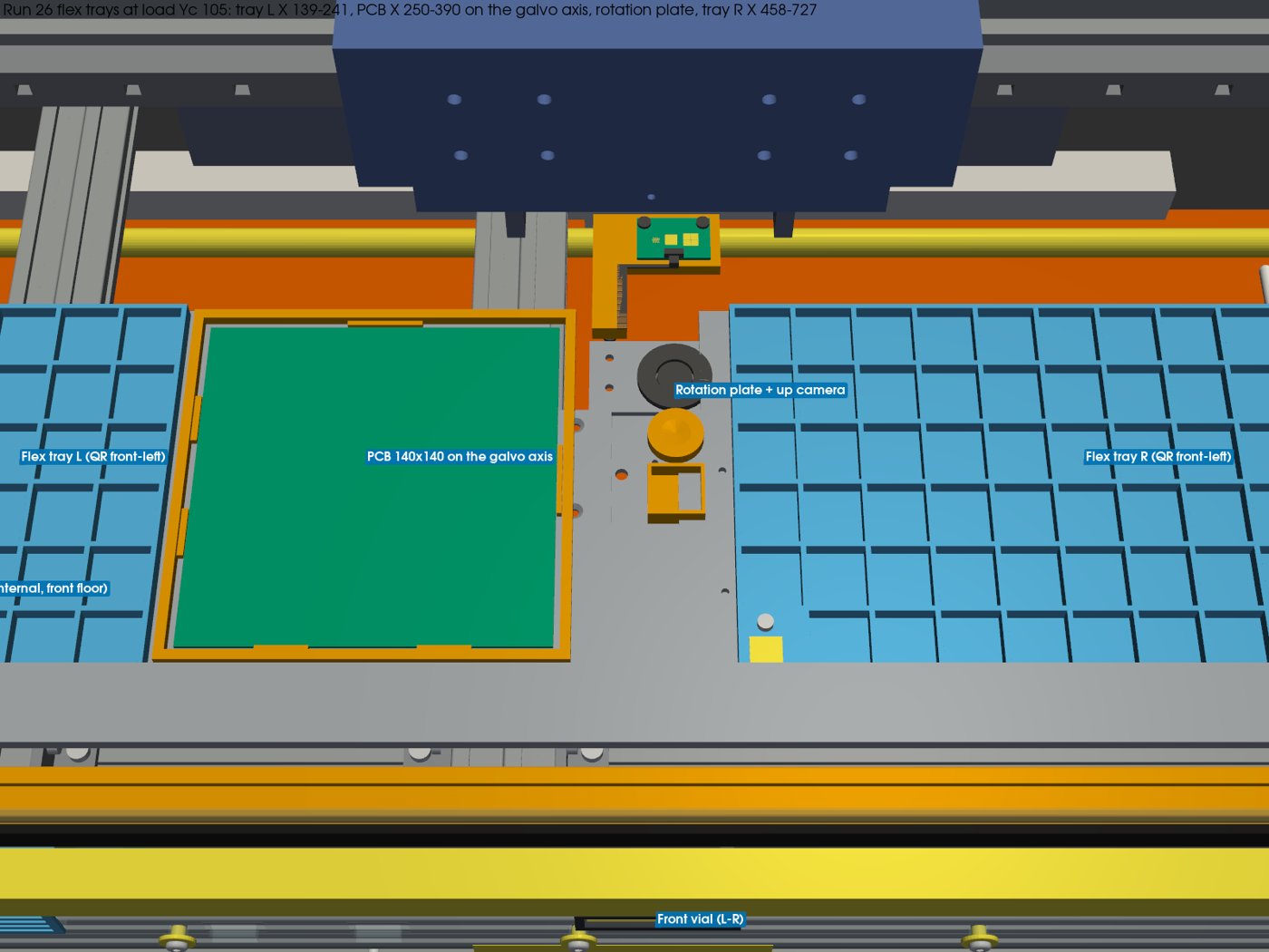
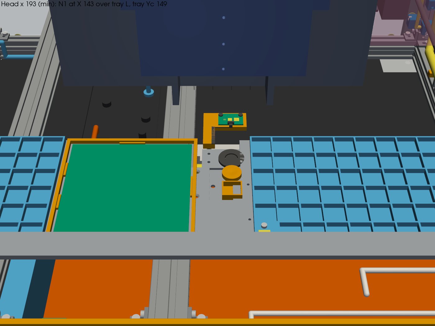
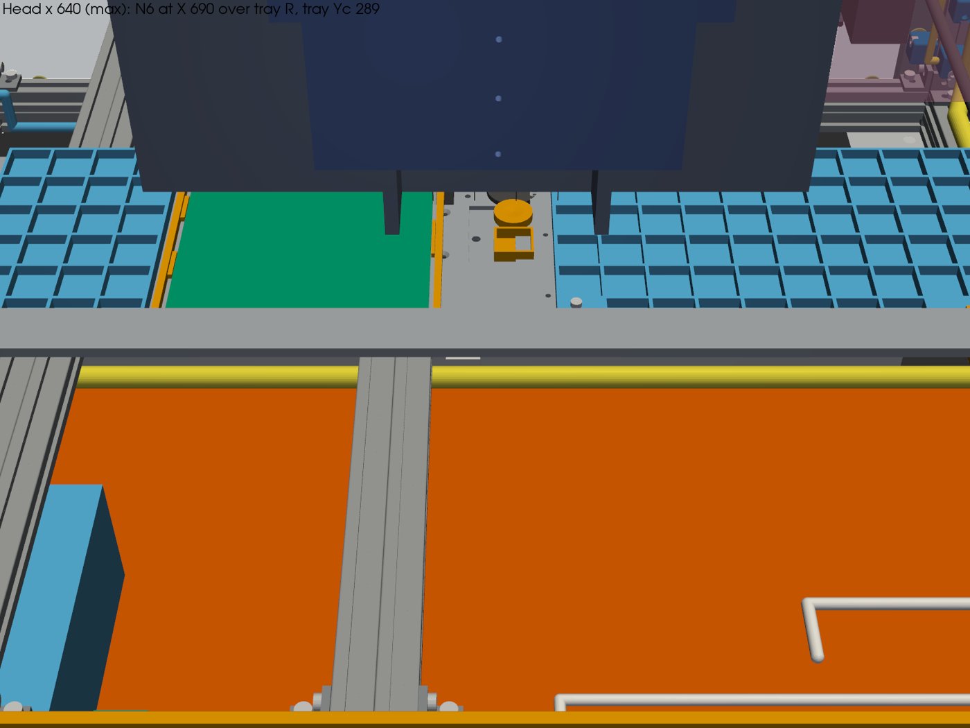
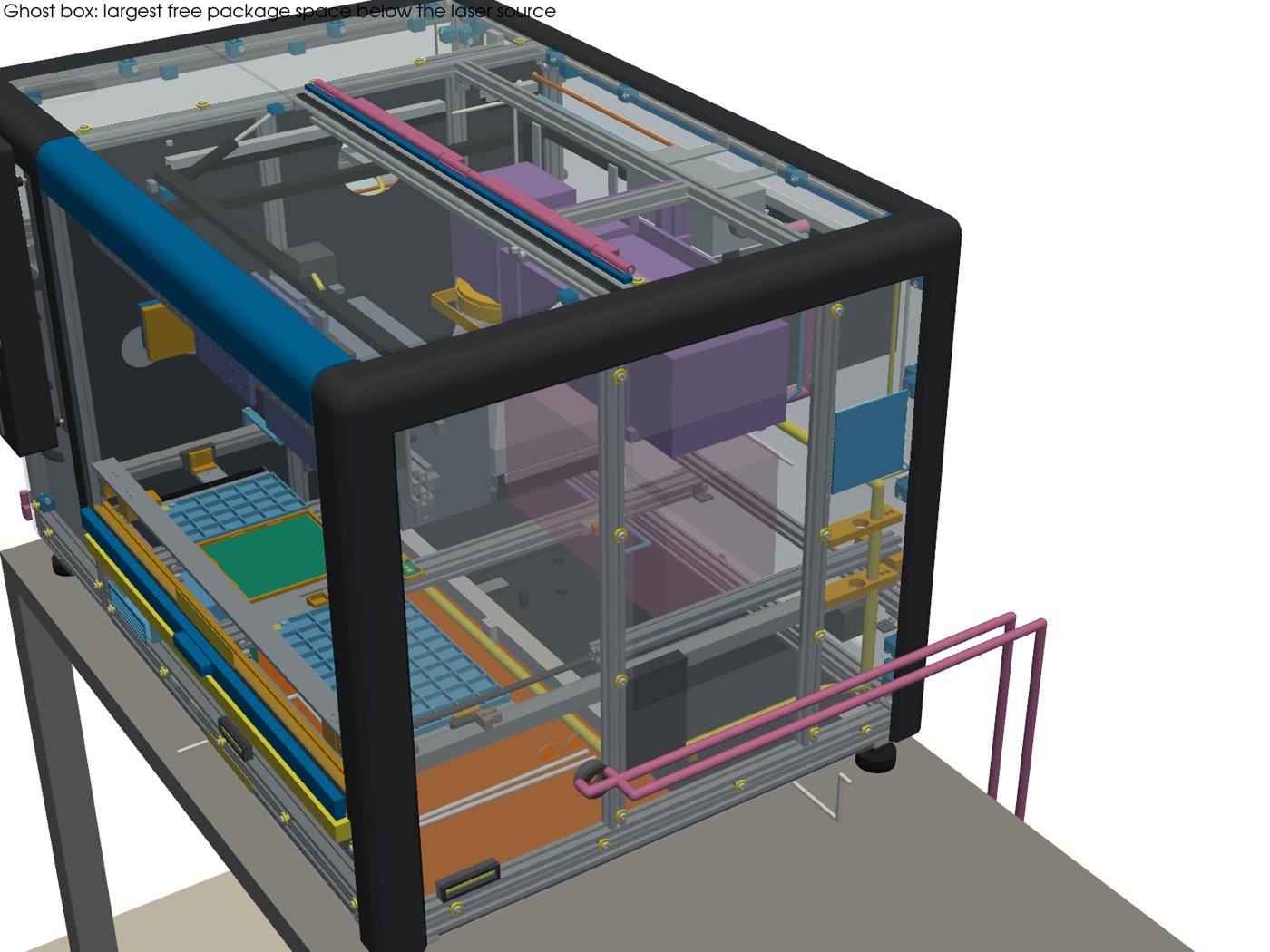
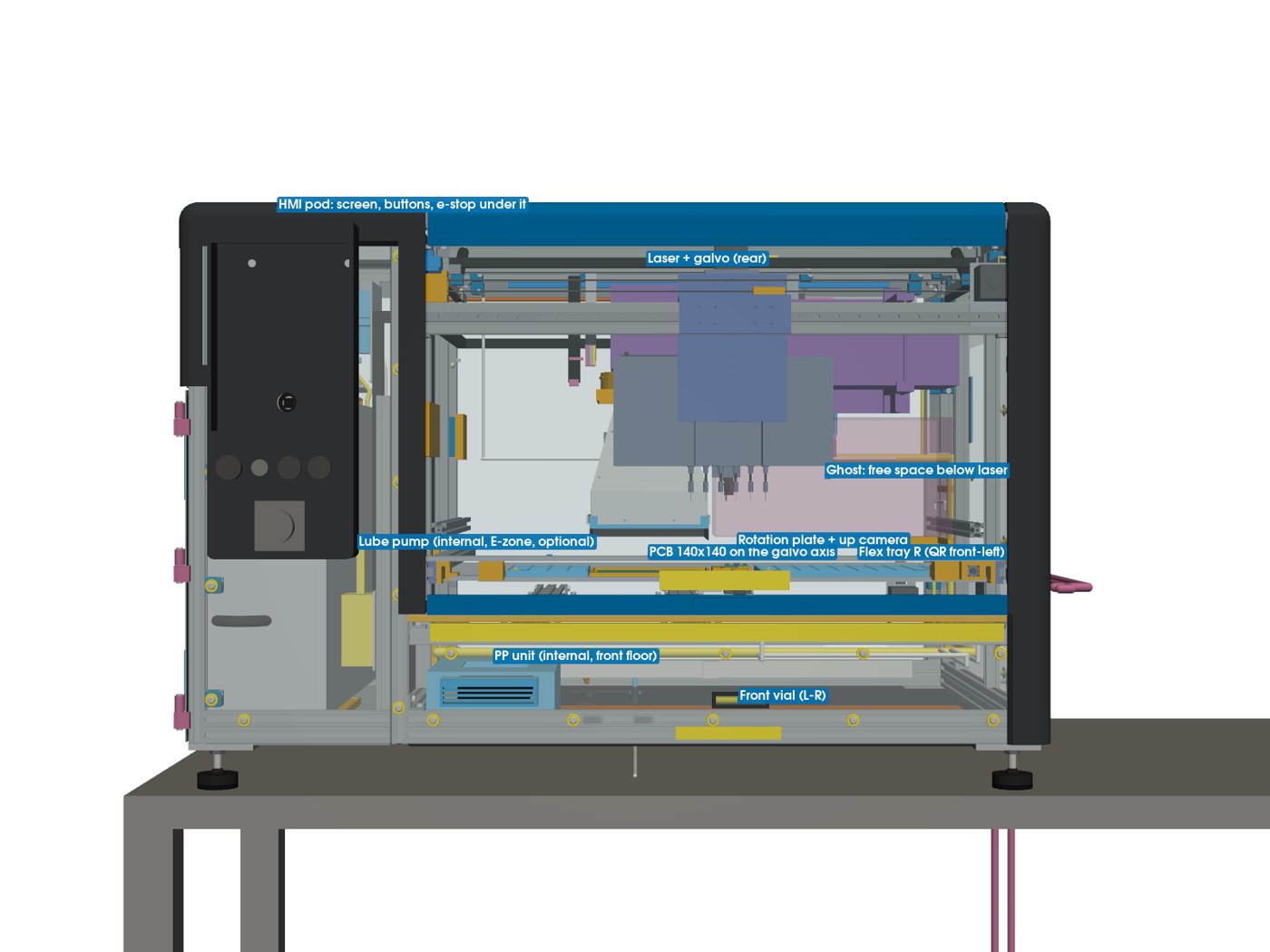
- One flexible tray system. The trays are now as big as they can be on each side of the PCB pocket, which stays on the galvo axis: tray L 102x162 mm (4x6 cells) and tray R 269x162 mm (11x6 cells). The same tray takes SMT or through-hole parts; the QR tag in the front-left cell tells the software which layout is loaded, and a mismatch blocks the job.
- Clear lids, resized. Clear anti-static acrylic lids, 25 mm tall, with a frosted finger tab, sized to the new trays.
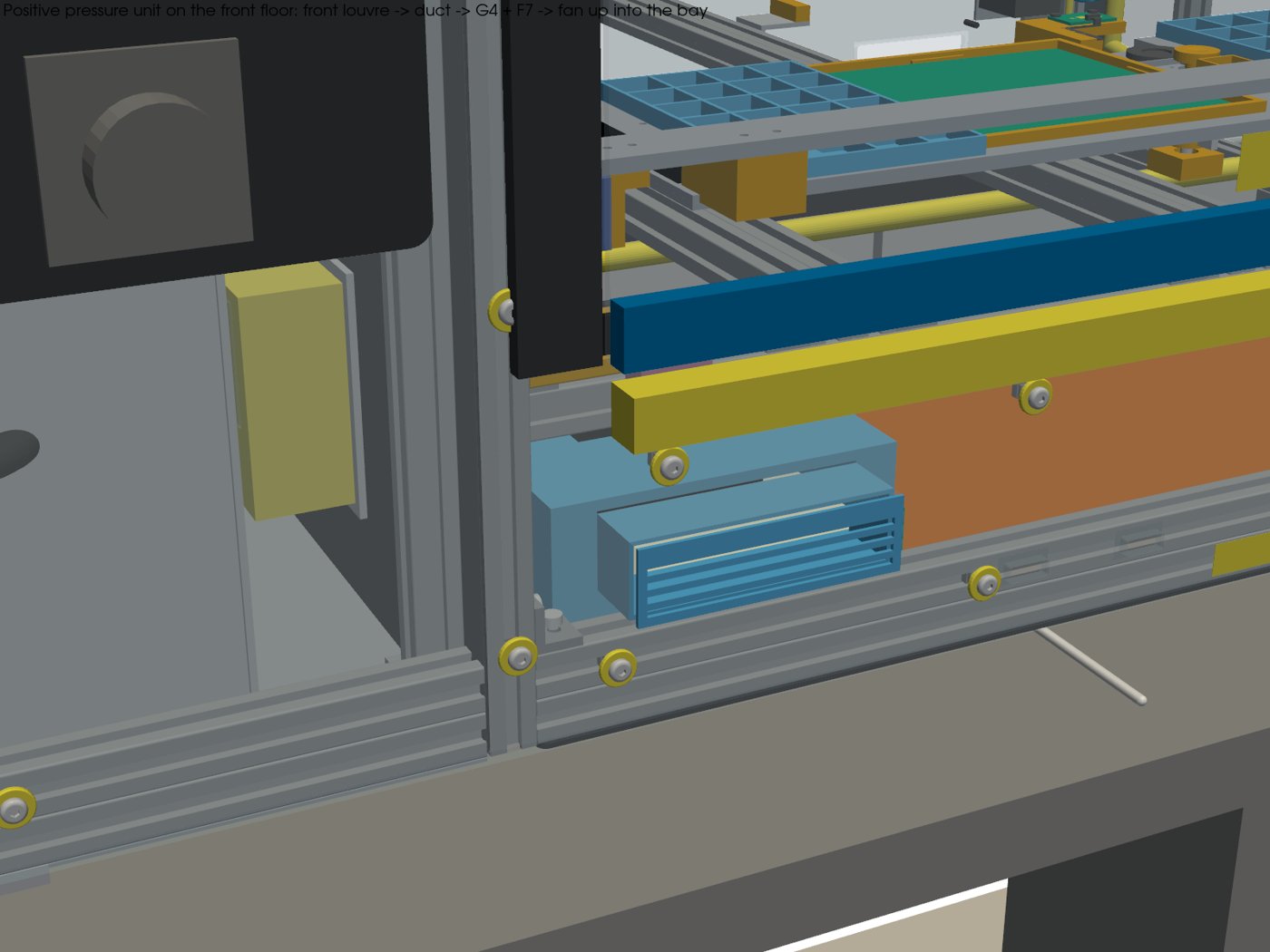
- Positive pressure inside. The filter and fan unit now sits on the front floor, fed through a louvre low in the front panel, with G4 and F7 filters.
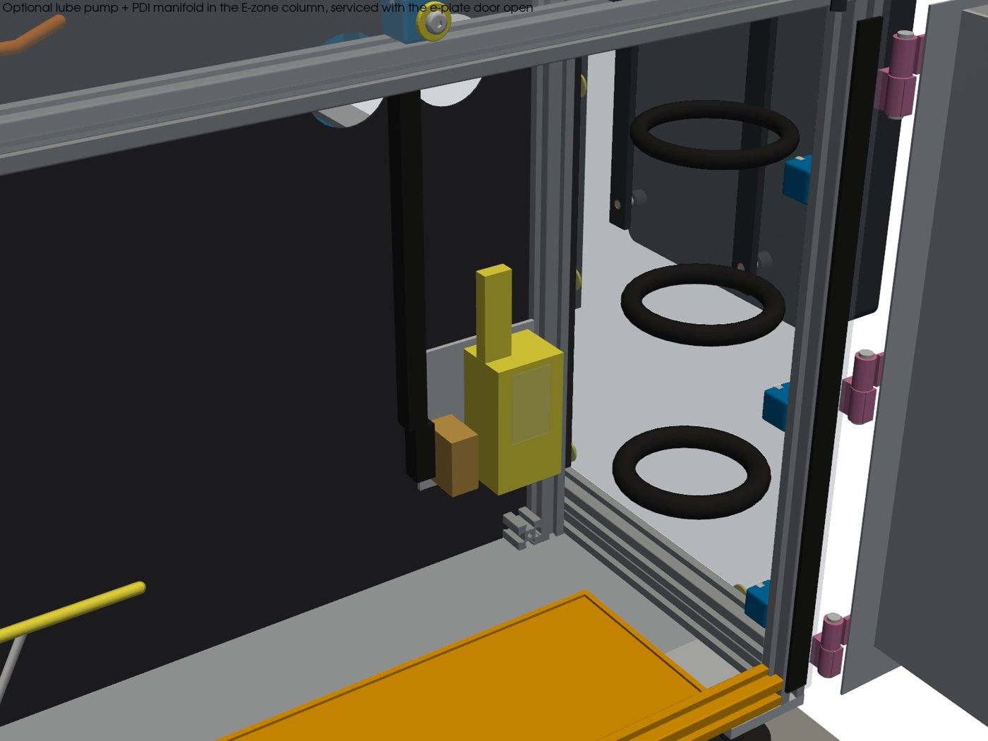
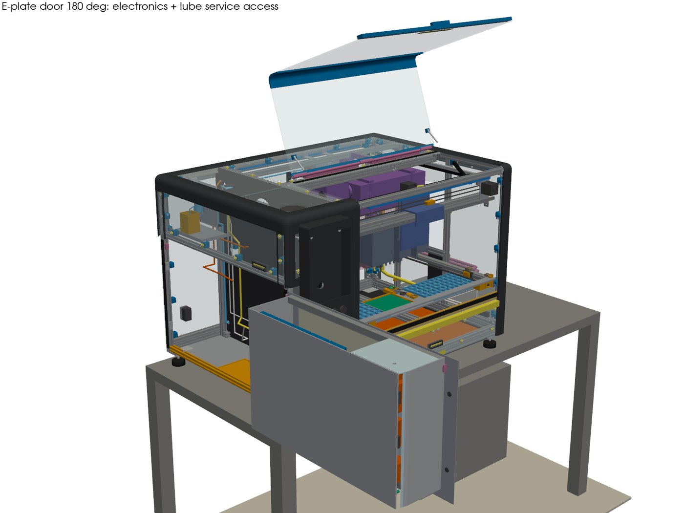
- Optional lube inside. The optional one-shot lube pump and its manifold sit in the electronics column, reached with the e-plate door open.
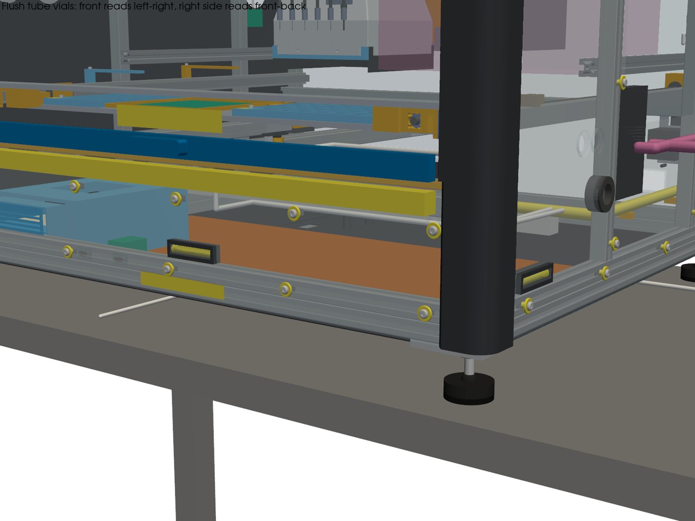
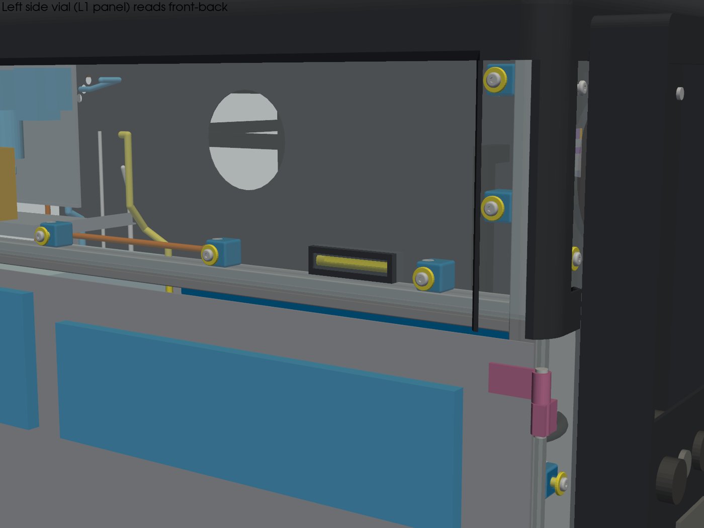
- Flush tube levels. Flush tube vials on the front (reads left-right) and on both sides (read front-back), all visible while you turn the feet.
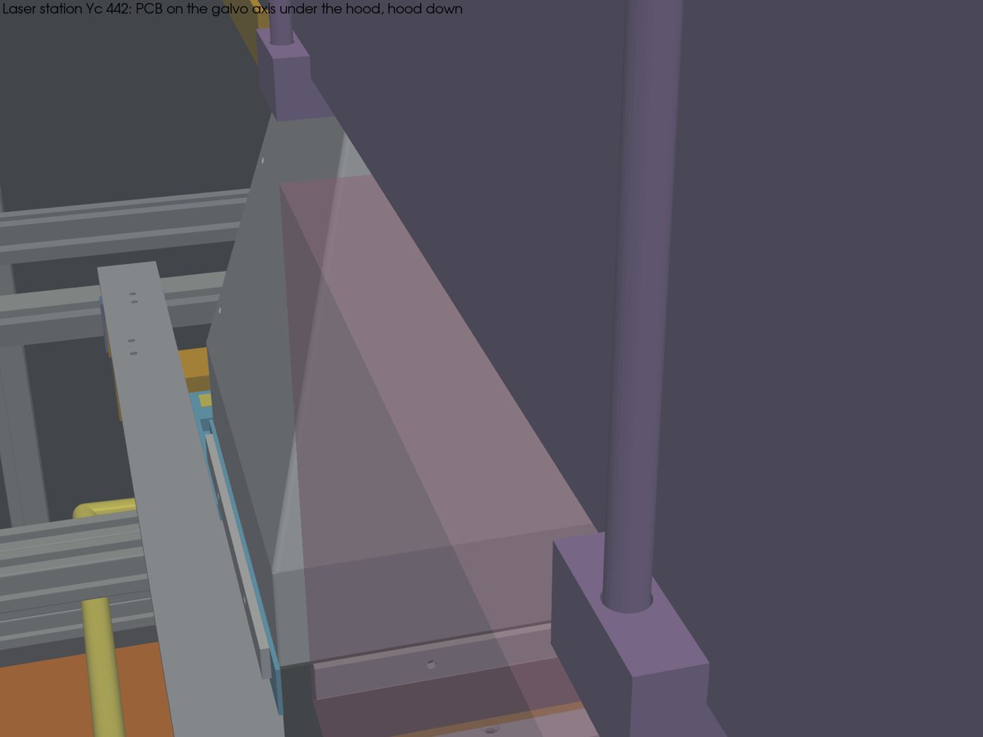
- Free space marked. The STEP carries a ghost box showing the largest free space below the laser source.
- Checks. Every moving part was swept again and the tip-over check was redone.
Animations (run 26)
Renders (run 26)
Downloads (run 26)
- osso_top_run26.step (panels incl. panel fasteners + components; ghost free-space box) (zip)
- osso_top_run26.glb (front_view camera)
- osso_top_run26.usdz
- Software rules SR-001 to SR-036
Run 25: every needle, everywhere
Run 25 (Nov 2, 2026). The board, the laser and the hood moved right, so every needle and the hot-air tip now reach every millimetre of the 140x140 PCB and the whole through-hole tray. No dead corners.
What's new in run 25
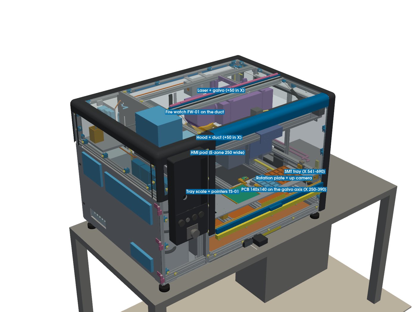
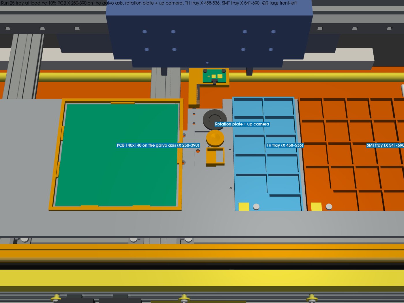
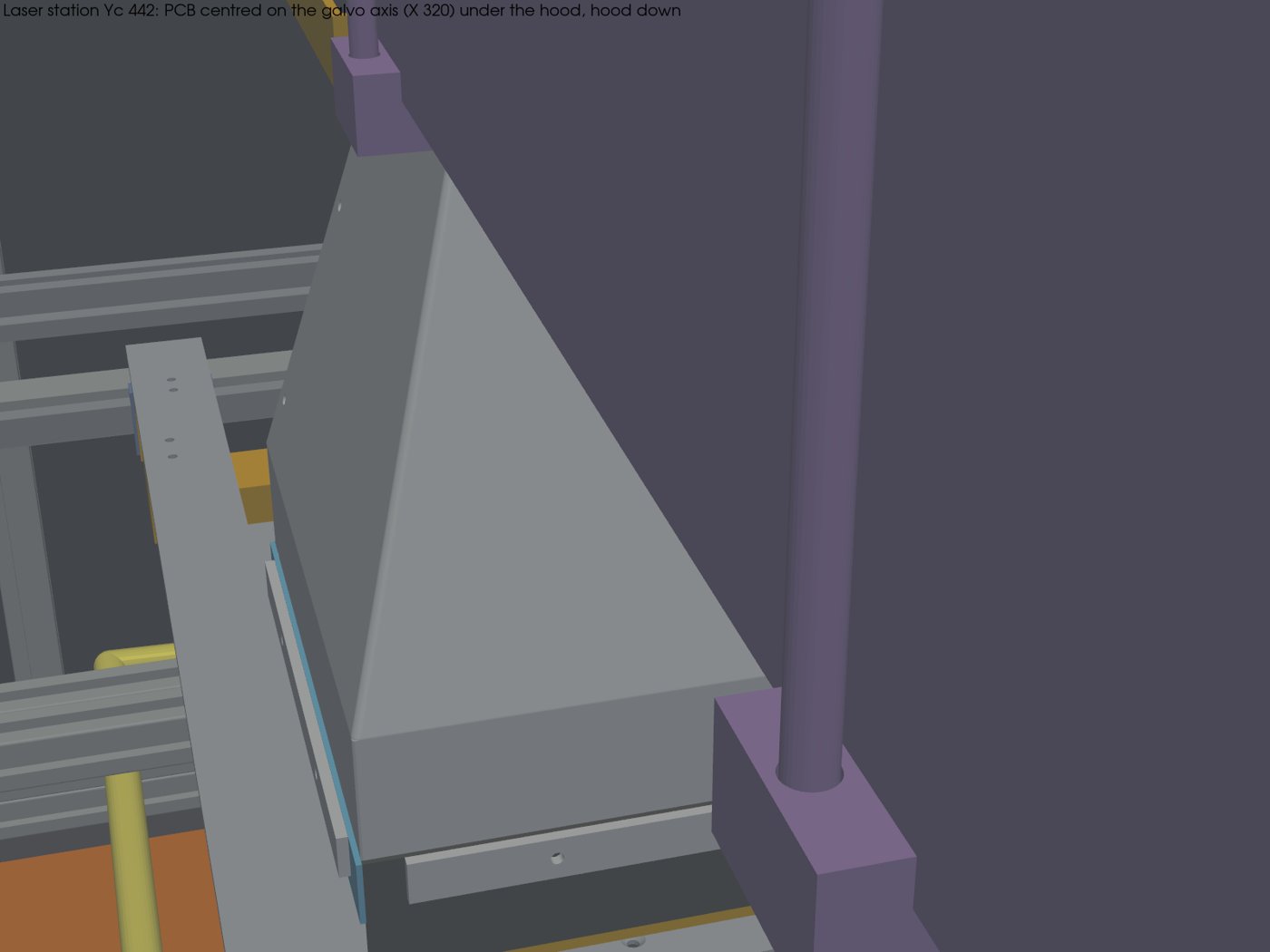
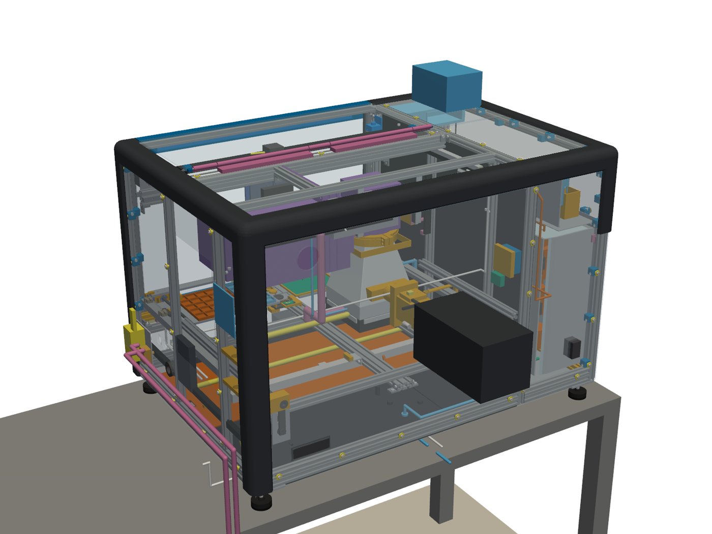
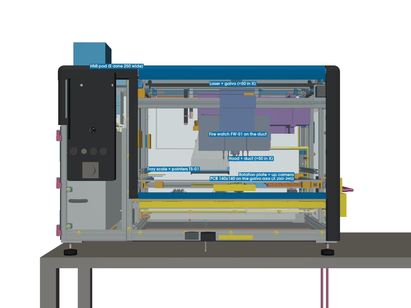
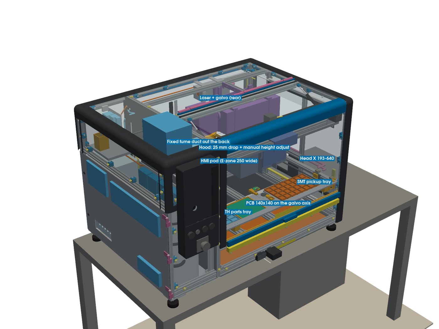
- Full reach. The PCB pocket, galvo, laser, hood and fume duct moved 50 mm to the right, with the PCB still centred on the galvo axis. All six needles and the hot-air tip cover 100 % of the board and 100 % of the through-hole tray; the SMT tray is fully covered too.
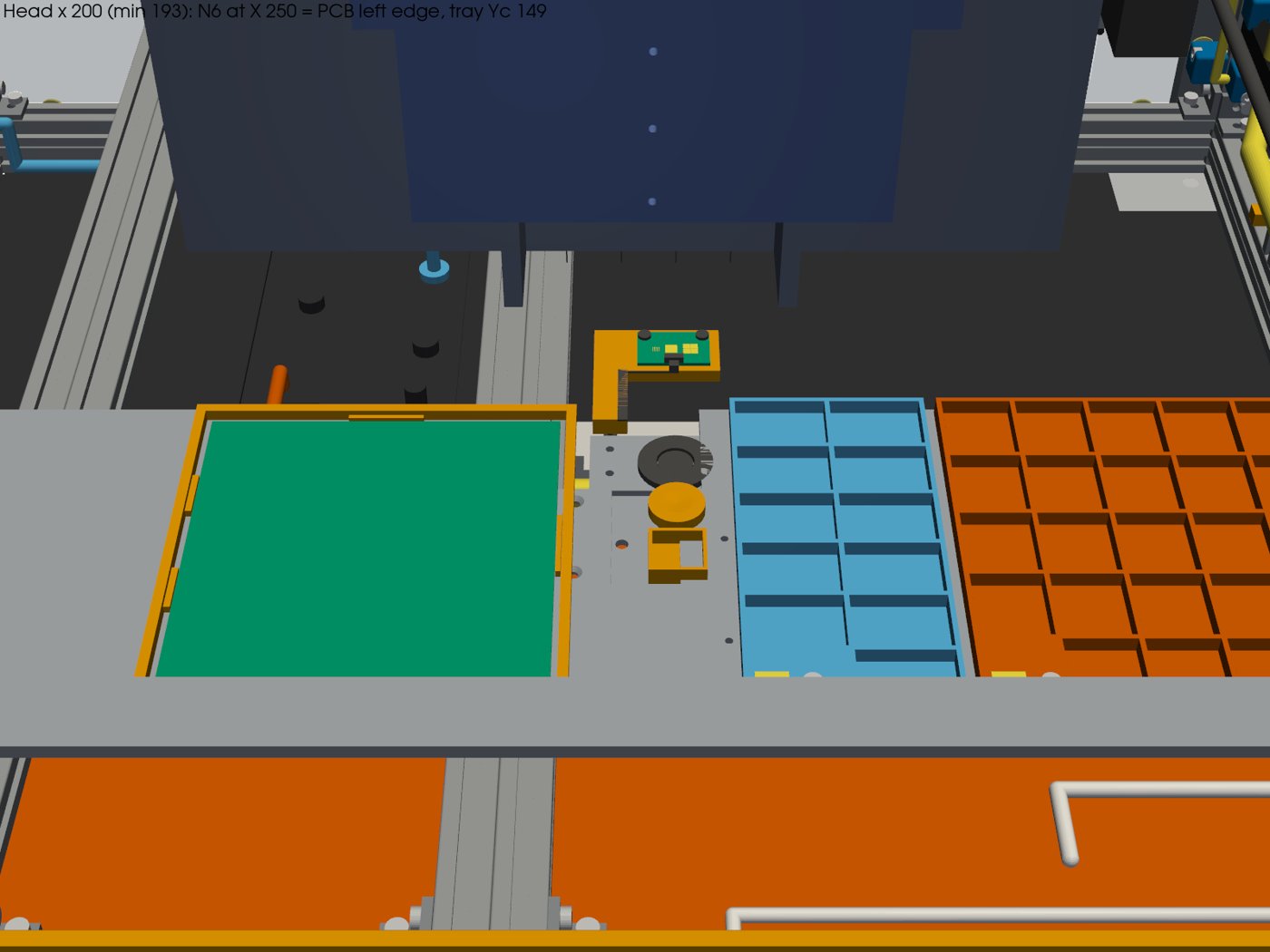
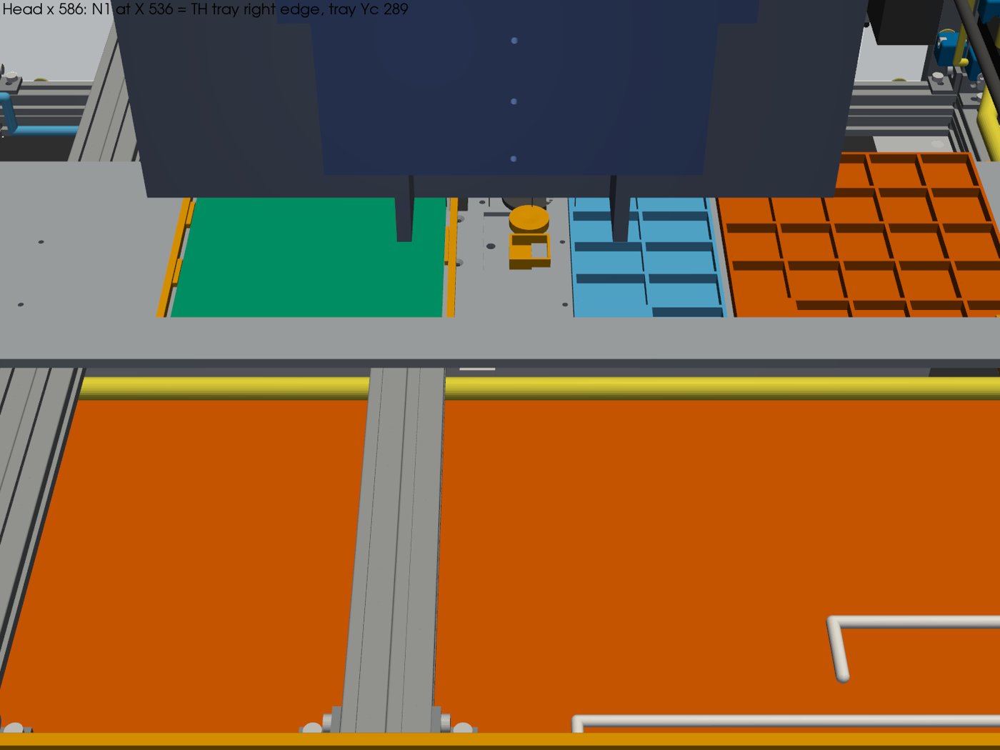
- A tidier tray. Left to right: the PCB, the rotation plate with the up-looking camera, the through-hole tray, the SMT tray. The angled crosshair camera and the up camera both work over the same single-PCB tray.
- Trays that identify themselves. Each part tray carries a QR tag in its datum corner. The camera reads it before a job, and the job will not start if the wrong tray is in.
- Job QR on the board. Every job PCB carries a small QR patch on both sides at the near edge, so the machine knows which job and which side it is looking at.
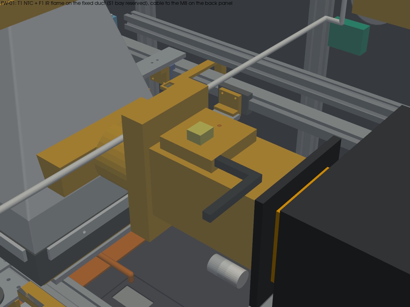
- Fire watch. A temperature probe and an IR flame sensor on the fumes duct latch the laser off in hardware. The extractor keeps running and the hood stays down.
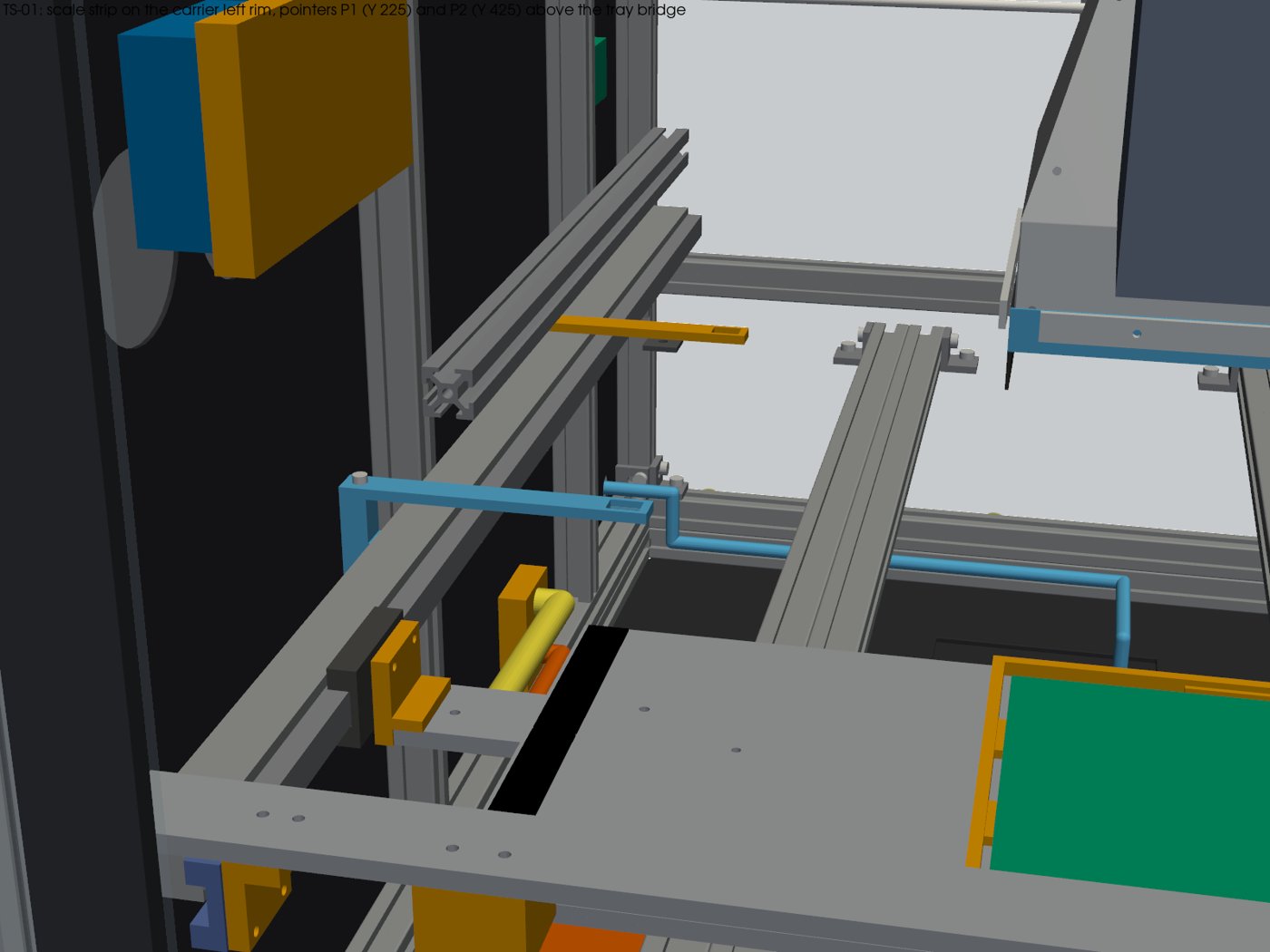
- Clear lids and a tray scale. Clear anti-static lids keep parts in place off the machine; the camera checks that they are off. A simple engraved scale and two pointers let you read the tray position by eye.
- Checks. Every moving part was swept again (door, electronics plate, tray, hood drop, head travel): no clashes. The tip-over check was redone.
Watch the reach sweep
Renders (run 25)
Downloads (run 25)
- osso_top_run25.step (panels + components subassemblies) (zip)
- osso_top_run25.glb (front_view camera)
- osso_top_run25.usdz
- reach sweep animation (USDZ)
- Run 25 tray layout and option integration drawing (PDF)
- Software rules SR-001 to SR-033
- PCB rules (job QR patch)
Run 24: one PCB on the galvo axis
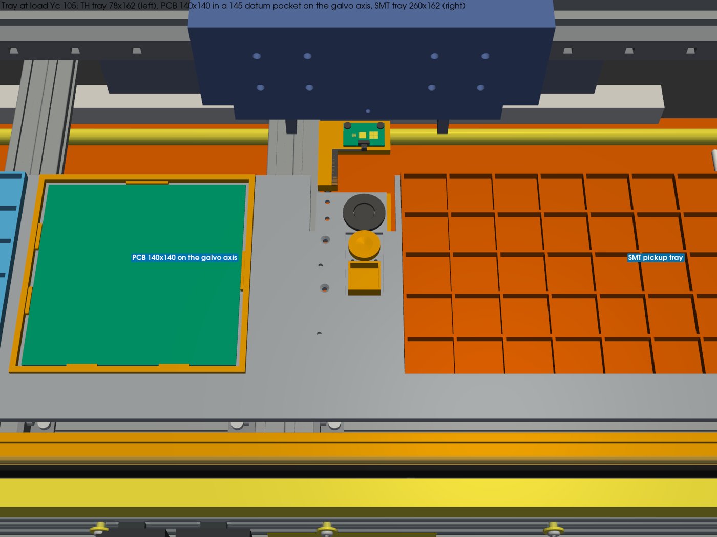
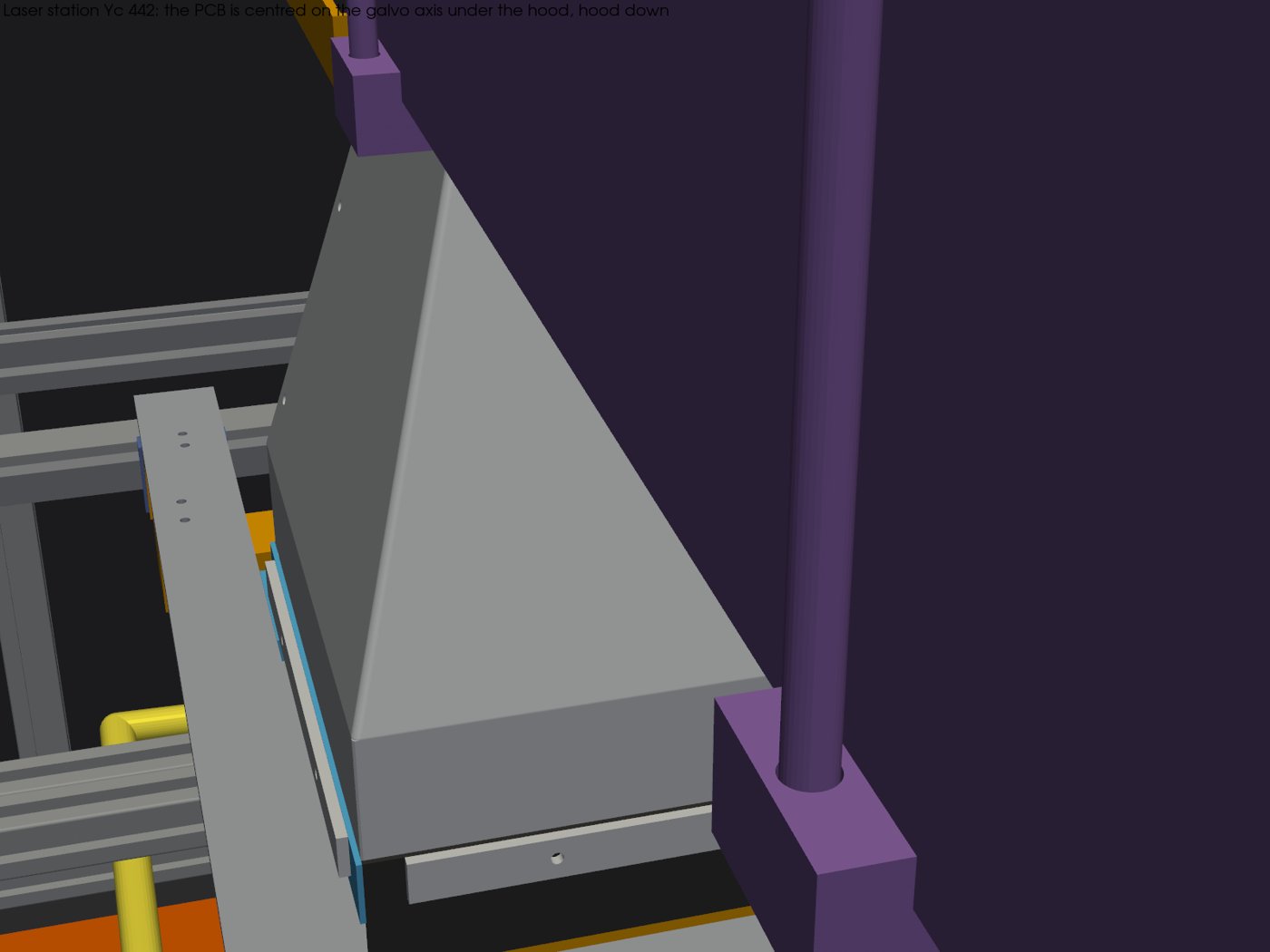
Run 24 (Nov 2, 2026): a single 140x140 blank in a 145x145 datum pocket centred on the laser axis, a through-hole tray on the left and an SMT tray on the right, and a calibrated laser offset.
Renders (run 24)
Downloads (run 24)
Run 23: hood height adjust and a wider electronics zone
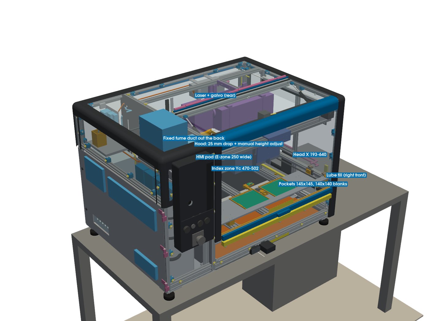
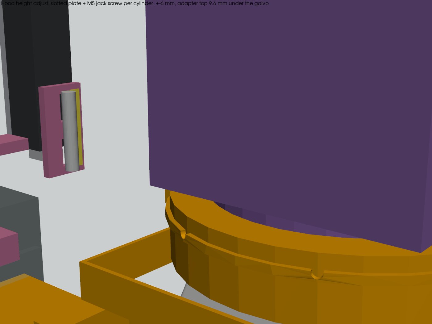
Run 23 (Nov 2, 2026): the hood height adjusts by +/-6 mm (focus first, then the hood), two 145x145 tray pockets, a longer head X travel, intakes on the e-plate door for the power supplies and drivers, and a 60 mm wider electronics zone.
Renders (run 23)
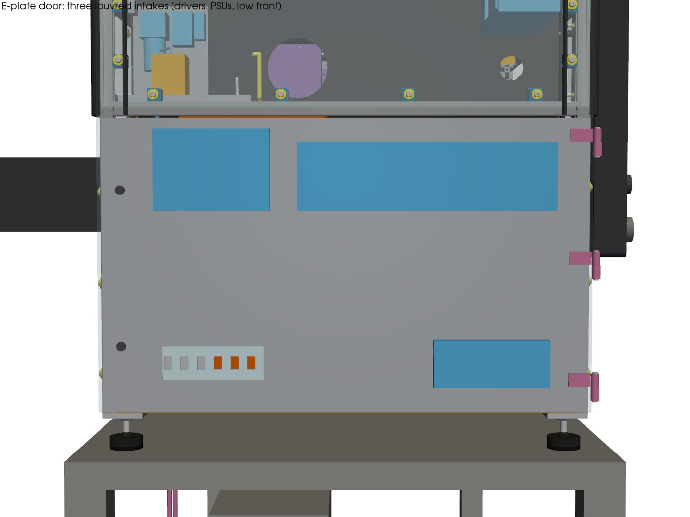
Downloads (run 23)
Run 22: hands on, hood off in one slide
Run 22 (Nov 1, 2026). Everything you touch is now right at the front, and the laser hood comes off with one sideways slide. No tools, no hoses to wrestle.
What's new in run 22
- Front HMI pod. The 10.1 in portrait touchscreen is back on the front, just under the fume exit, in a slim printed pod. The key switch, emission lamp, START, HOLD and the e-stop sit directly under the screen, so status and controls are in one place, readable with the gull-wing door open.
- Hood quick-disconnect as one slide. The hood hangs on two short rails under the fixed galvo collar. Slide it toward the right-hand lane: in the first 5 mm three steel balls climb out of their cone, V and flat seats and lift it 3 mm, so the silicone seal clears the frame. A click at +45 mm, and at +55 mm it is free and lifts out.
- Sealed means sealed. At the home click the hood outlet presses onto a fixed EPDM face gasket on a rigid duct to the wall. No flex hose. A coded interlock sensor at that click is in the laser enable chain: the laser cannot fire unless the hood is seated.
- Repeatable. The kinematic seats put the hood back in the same place every time; a spring-ball detent gives the sealed and open clicks.
- Checks. The hood slide is swept along its whole path, the head is swept along X past every new part, the door, e-plate and tray sweeps are rerun, and the tip-over check is redone.
Watch the slide
Renders (run 22)
Downloads (run 22)
Run 21
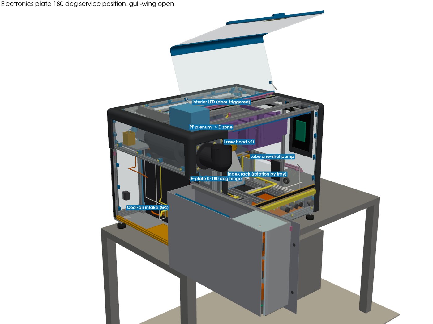
Run 21 (Nov 1, 2026): the rotation plate indexed by the tray itself (rack and pinion with a one-way clutch, one motor fewer), door-triggered interior LEDs, a one-shot metered lube pump outside the right panel, a cool-air intake past the electronics, and a 0 to 180 deg e-plate.
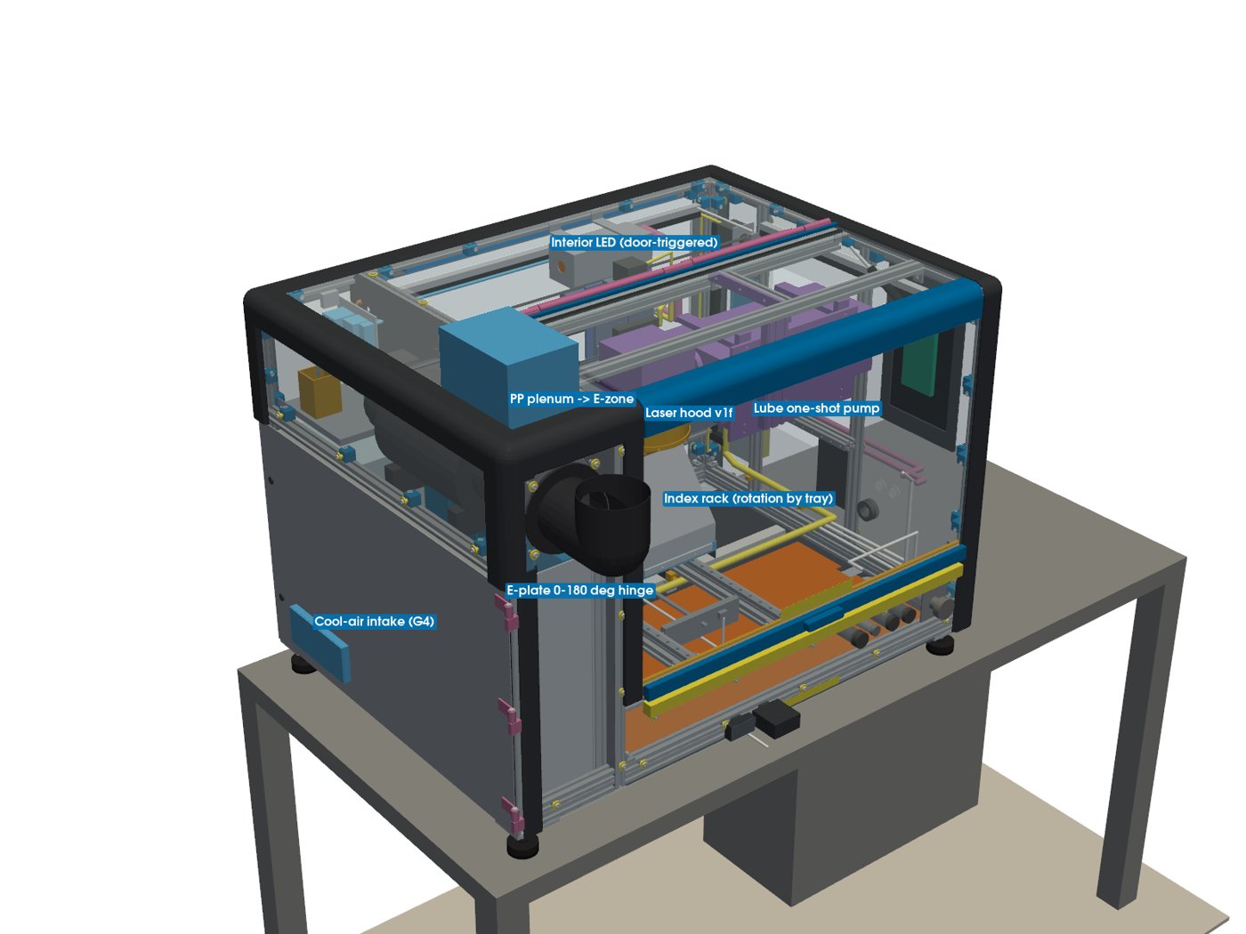
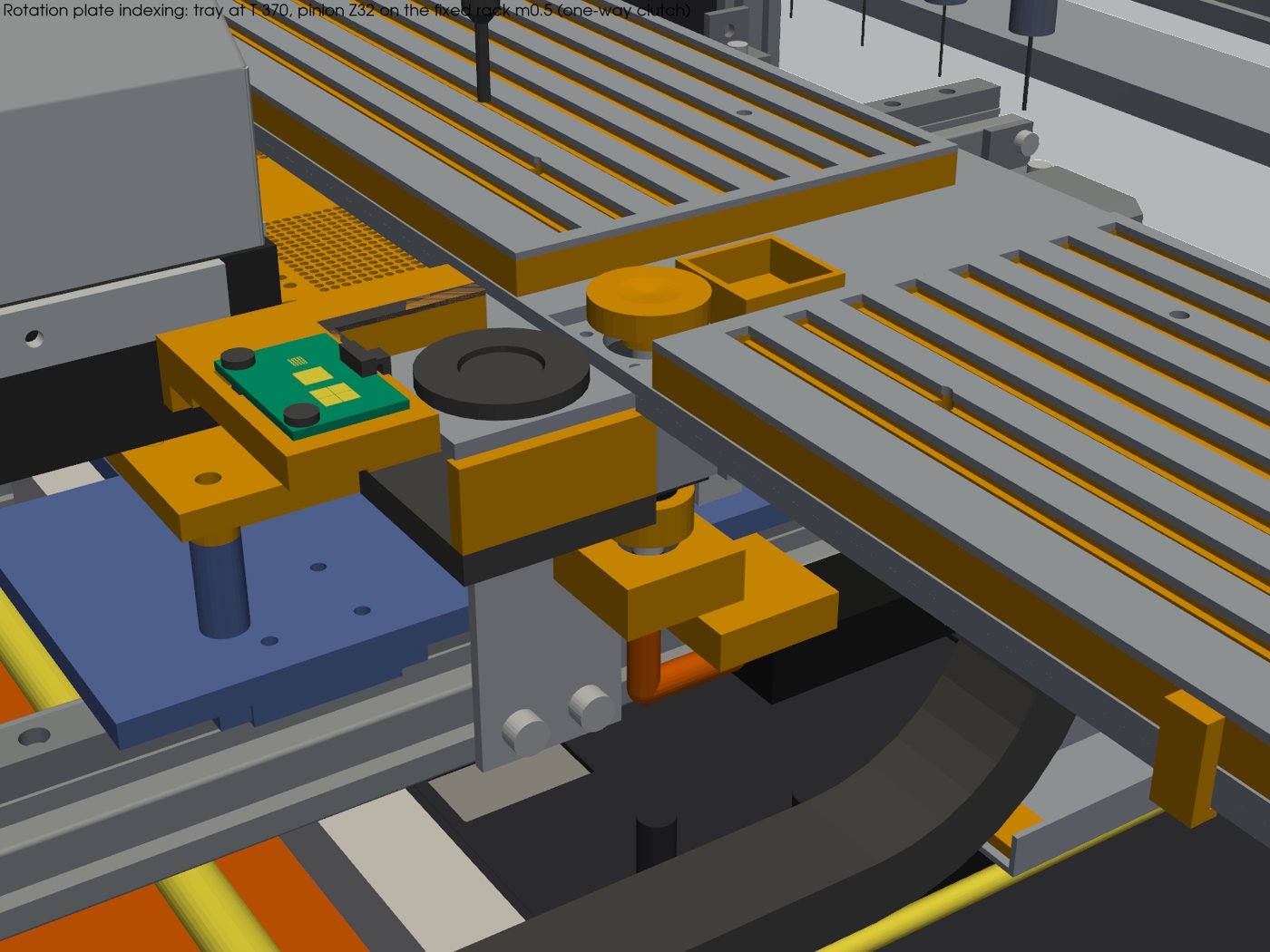
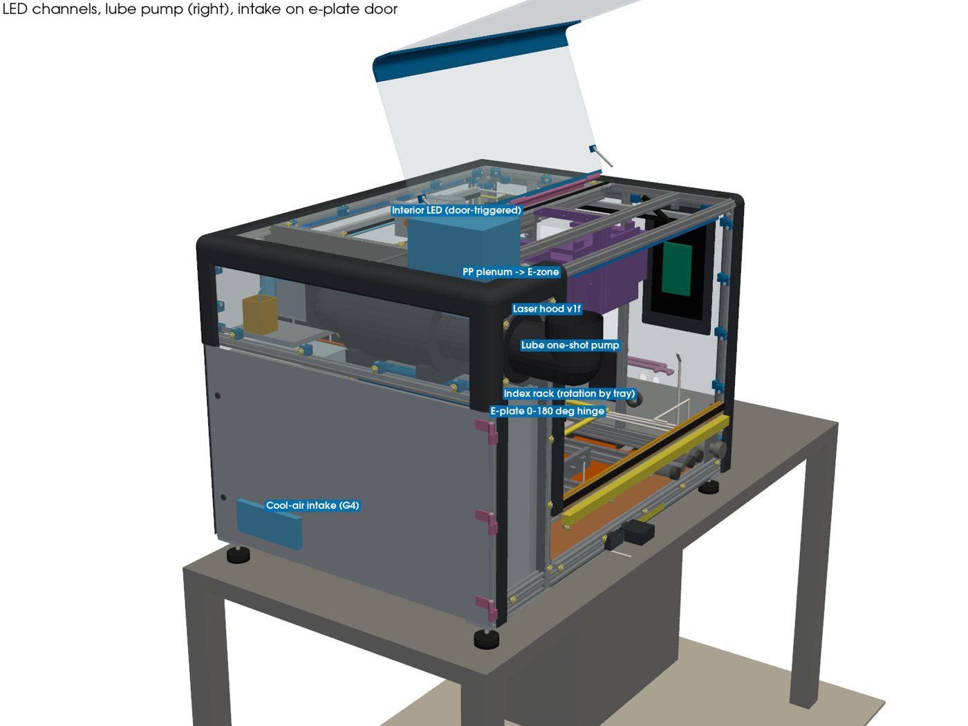
Downloads (run 21)
Run 20
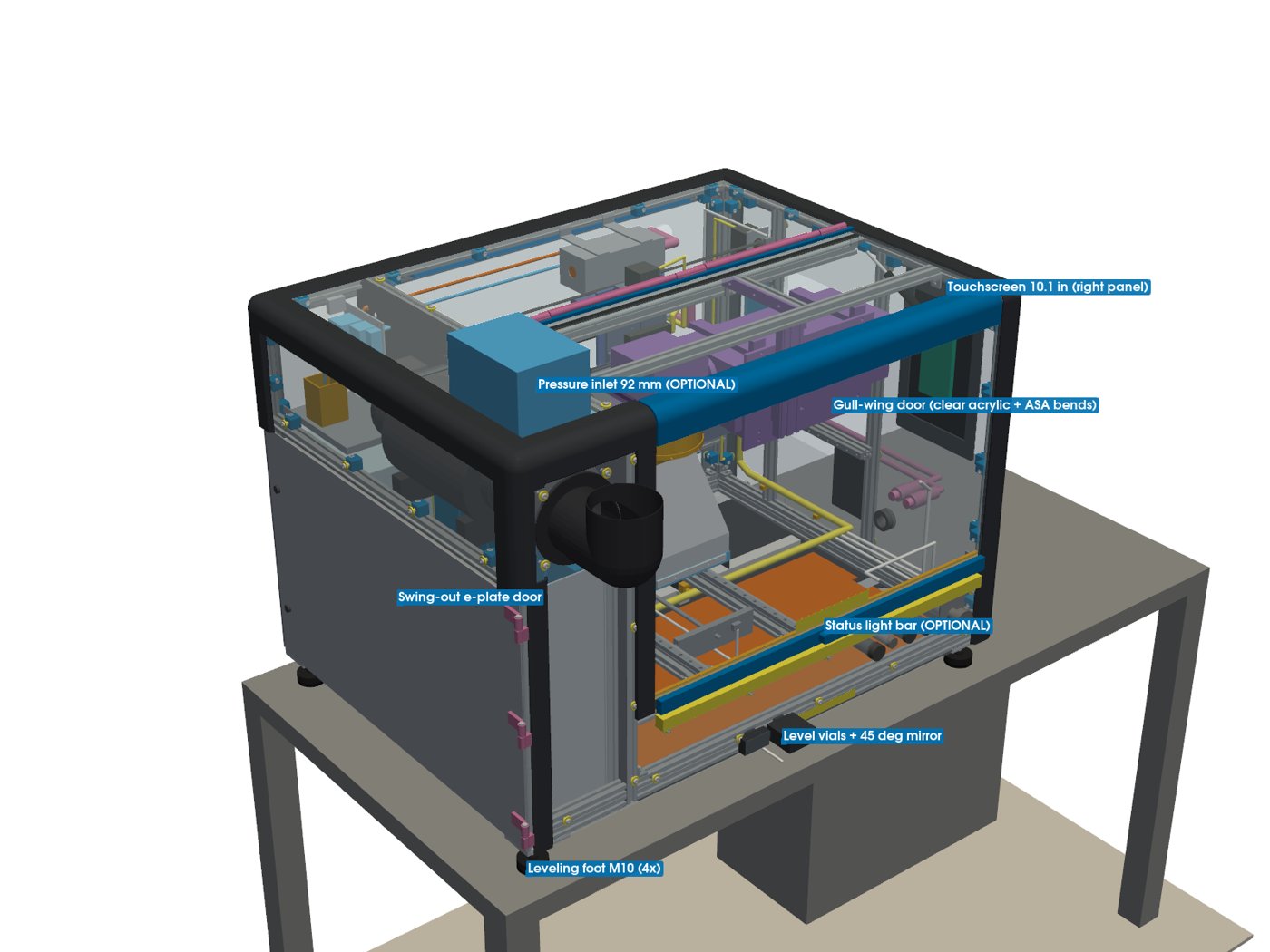
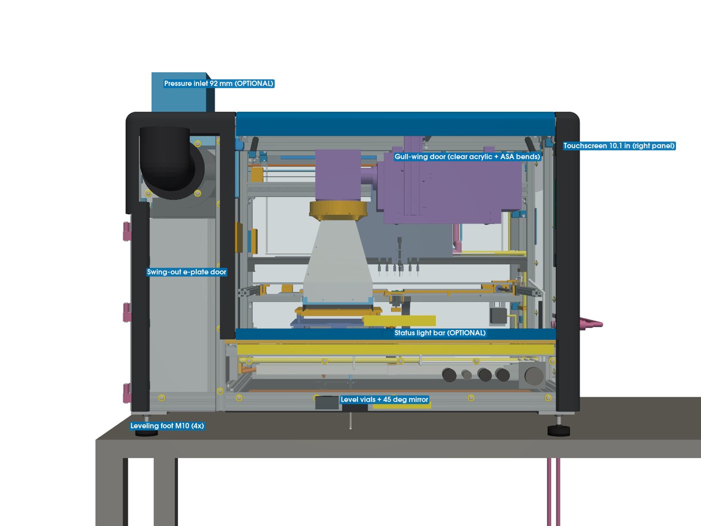
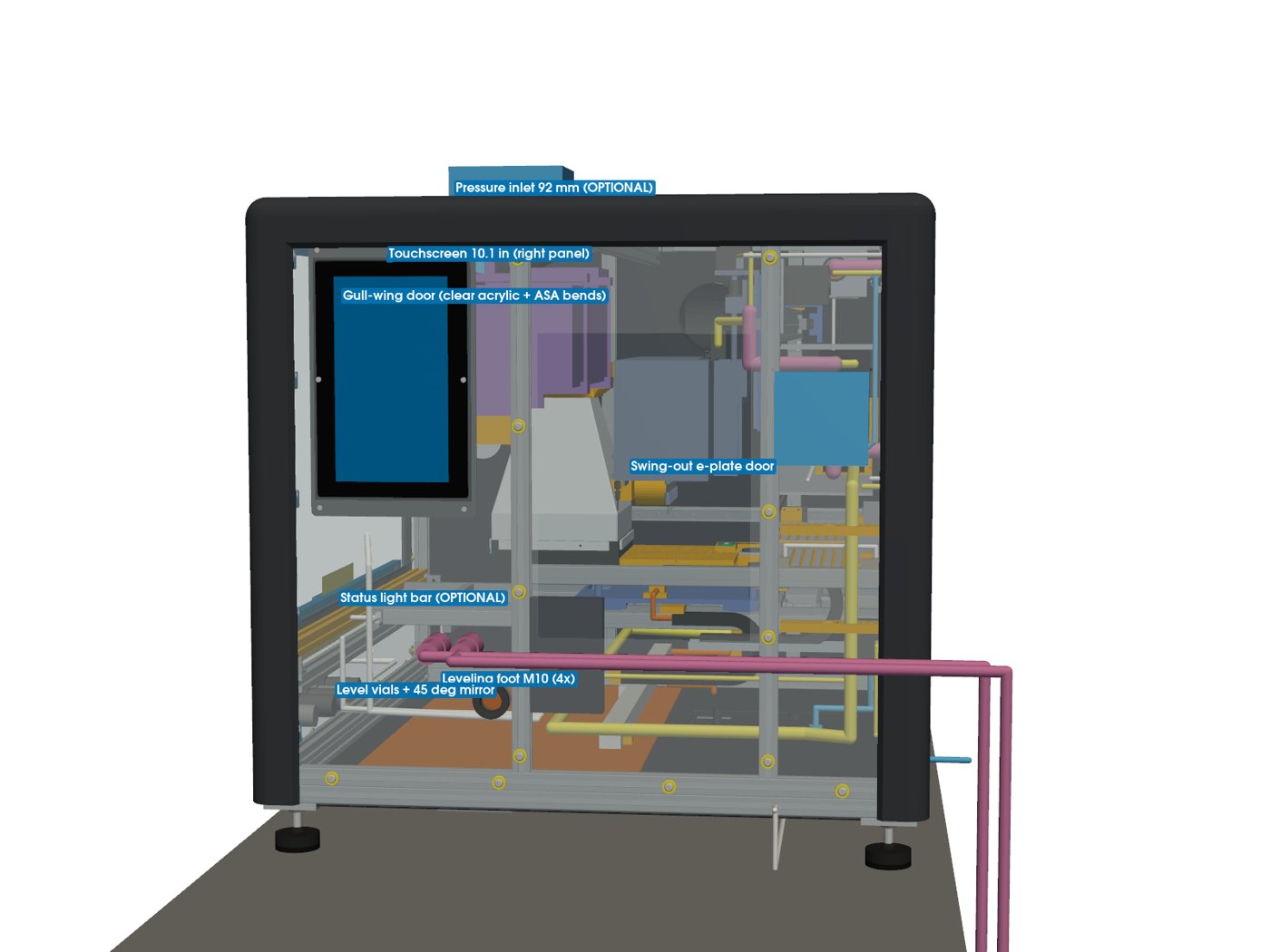
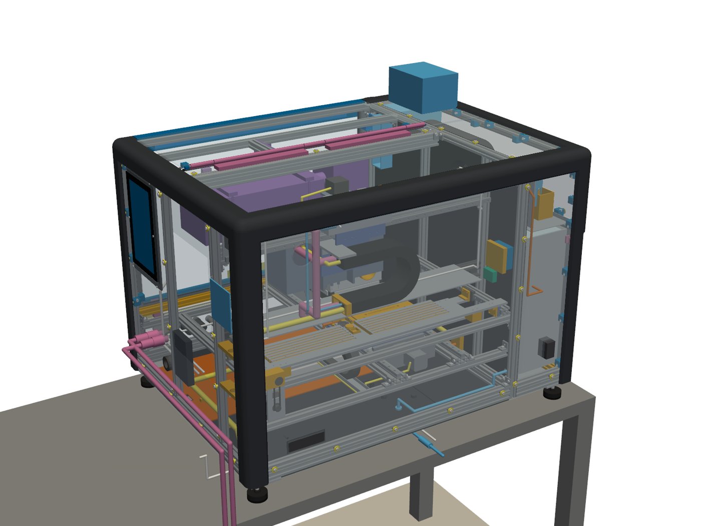
Run 20 (Nov 1, 2026): run 19 plus the laser hood v1f, enclosure v2 and the approved options. It is shown with every option fitted; the optional modules are marked OPTIONAL and can be left out.
What changed in run 20
- Laser hood v1f: printed ASA galvo collar and sheet adapter, formed 1.0 mm 5052 shell (bends R1.0 inside, K 0.40, seam tab as in the flat pattern), silicone band high on the frame side only and low on the other three, working distance a parameter (240 mm nominal). The laser fires only when sealed.
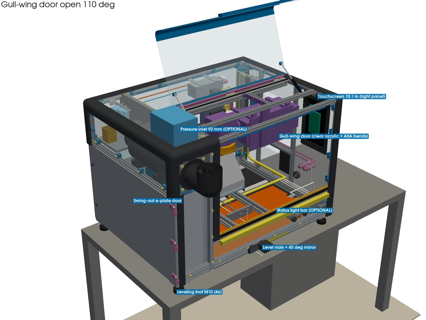
- Enclosure v2: clear 5.4 mm acrylic panels, detailed 2020/2040 T-slot extrusions with M3/M5 hardware, printed ASA R23.4 corner covers, 10.1 in touchscreen on the right panel.
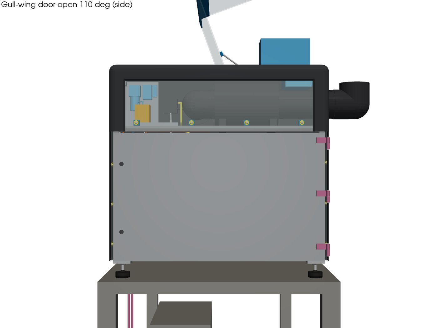
- Gull-wing door: 708 mm wide, top hinge, opens 110° on two 80 N gas struts (165 mm closed, 270 mm open), EPDM seal, two coded interlock sensors.
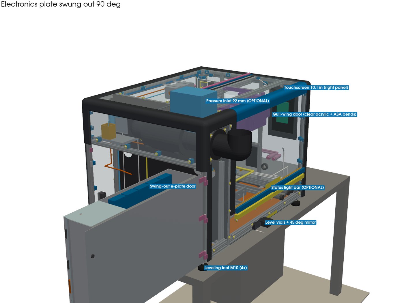
- Swing-out electronics plate: front-left hinge, 90° open, keyed quarter-turn latches, interlock, mains inlet on the back panel. Cable routing is not designed yet.
- Leveling feet: 4x M10 ball-swivel feet on 8 mm aluminum corner plates (58 mm nominal), two glass vials with a 45° mirror on the front bottom rail, a "do not lean" label; the accelerometer is on the electronics PCB.
- Positive pressure (OPTIONAL): 92 mm filtered inlet (G4/F7) at the top front of the electronics zone, diffuser, reversed cabinet fans, fume fan controller, pressure sensor.
- Status light bar (OPTIONAL): 700 mm, under the door.
- Checks: door swept 0 to 110° and electronics plate 0 to 100° against the whole machine; static clash check of every new part. See the downloads for details.
Animations (run 20)
Renders (run 20)
Downloads (run 20)
- osso_top_run20.step (run 20 STEP: panels + components, options as OPTIONAL_* subassemblies) (zip)
- osso_top_run20.glb (front_view camera) (zip)
- osso_top_run20.usdz (zip)
- gull-wing door animation (USDZ)
- e-plate swing animation (USDZ)
- Software rules SR-001 to SR-013
Run 19
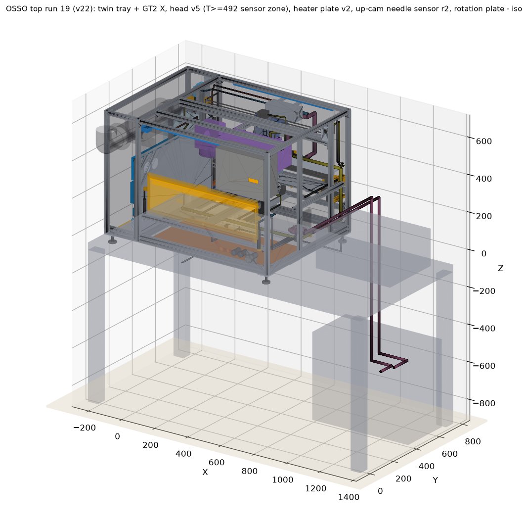
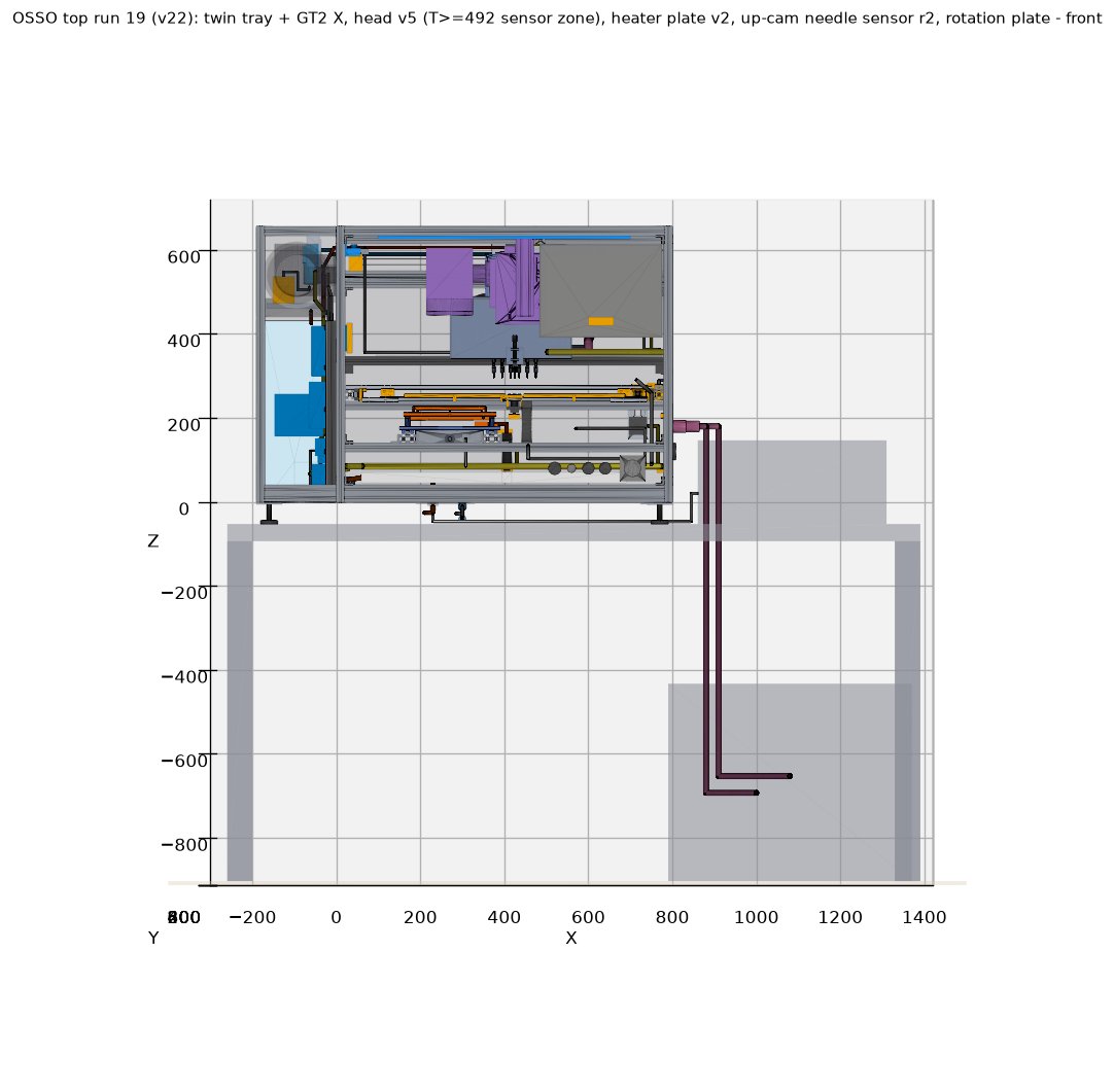
Run 19 (Oct 31, 2026, snapshot v22).
What changed in run 19
- Twin tray + GT2 belt X (run 18): two pairs of 240 mm cassettes on a laser-cut carrier, belt-driven X axis.
- Head v5 with the needle-sensor zone rule: needles go down at X 330 to 490 below Z 380 only when the tray position T ≥ 492 mm.
- Heater plate v2: 174 x 150 aluminum plate with two edge-band cartridge heaters, seated on the bed plate.
- Up-camera needle sensor r2: ENIG pad-array board mounted on the rotation-plate / up-camera bracket.
- Rotation plate module in the tray centre bay.
Renders (run 19)
Downloads (run 19)
- osso_top_run19.step (run 19, full top-level STEP) (zip)
- osso_top_run19.glb (run 19) (zip)
- osso_top_run19.usdz (run 19) (zip)
Run 16
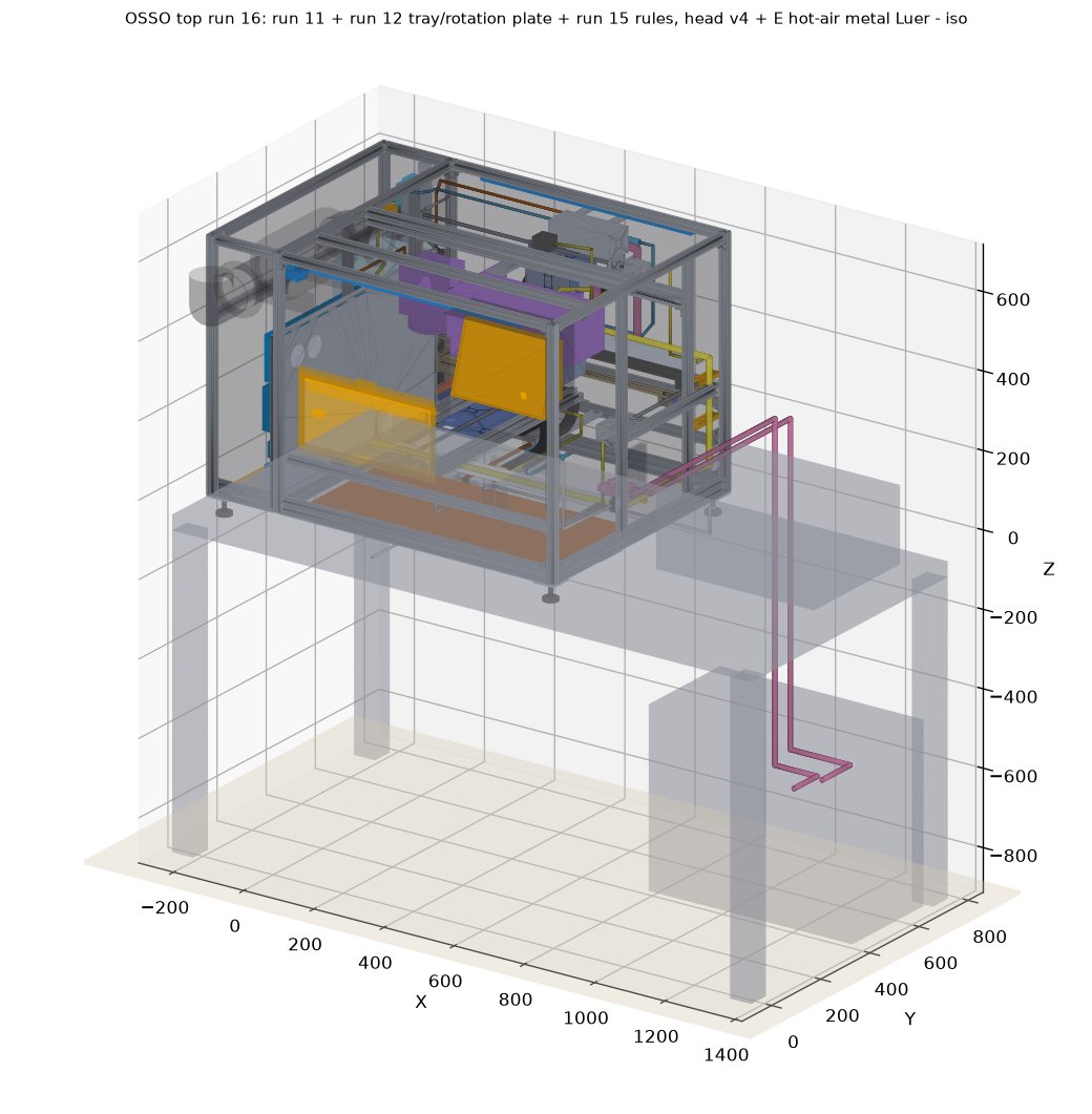
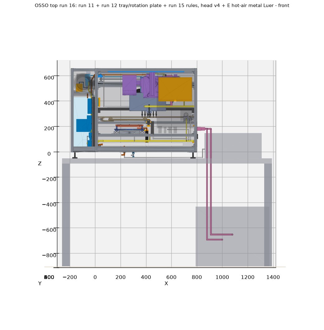
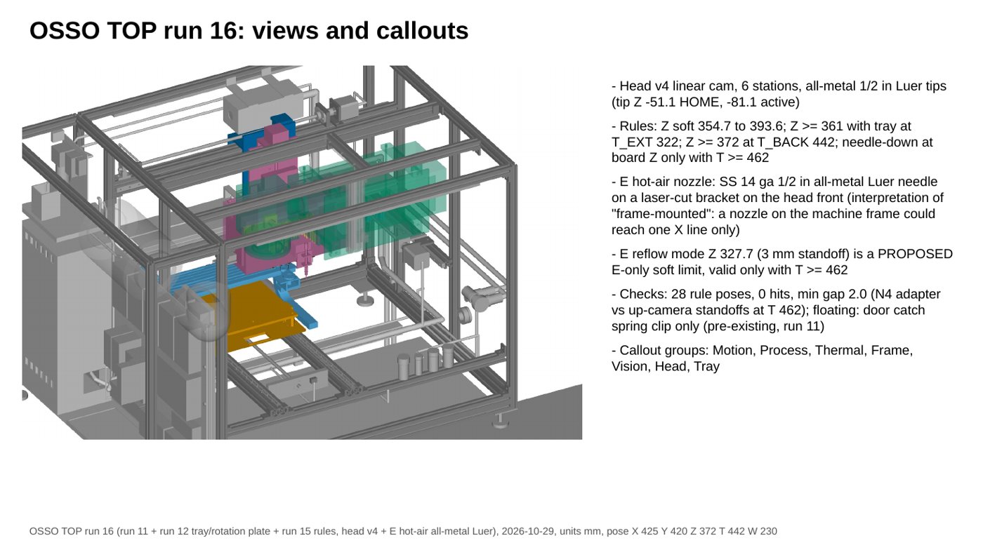
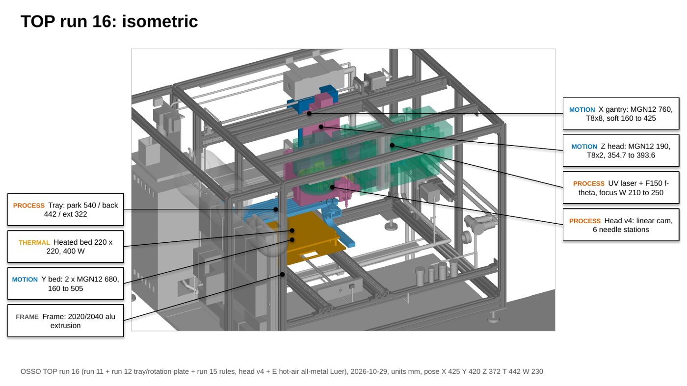
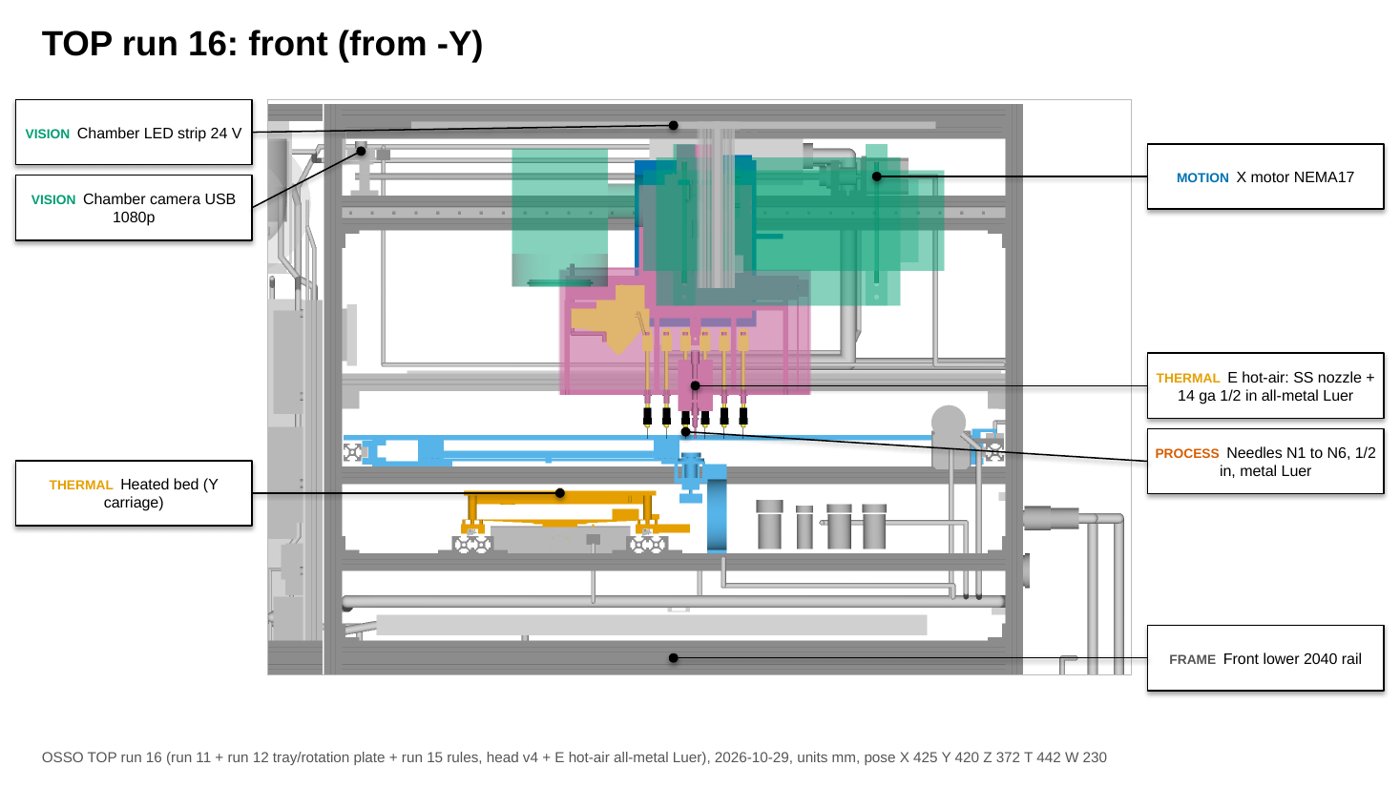
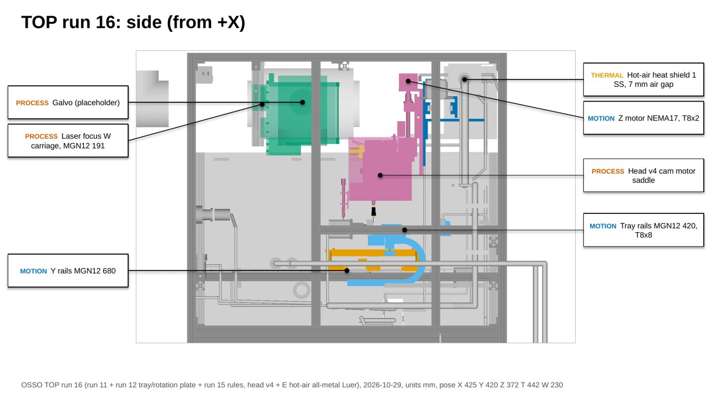
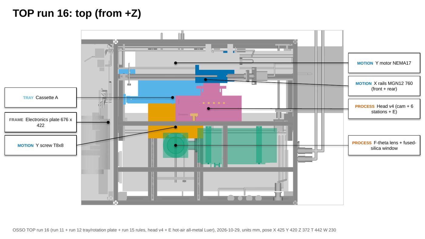
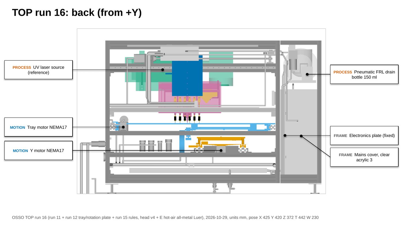
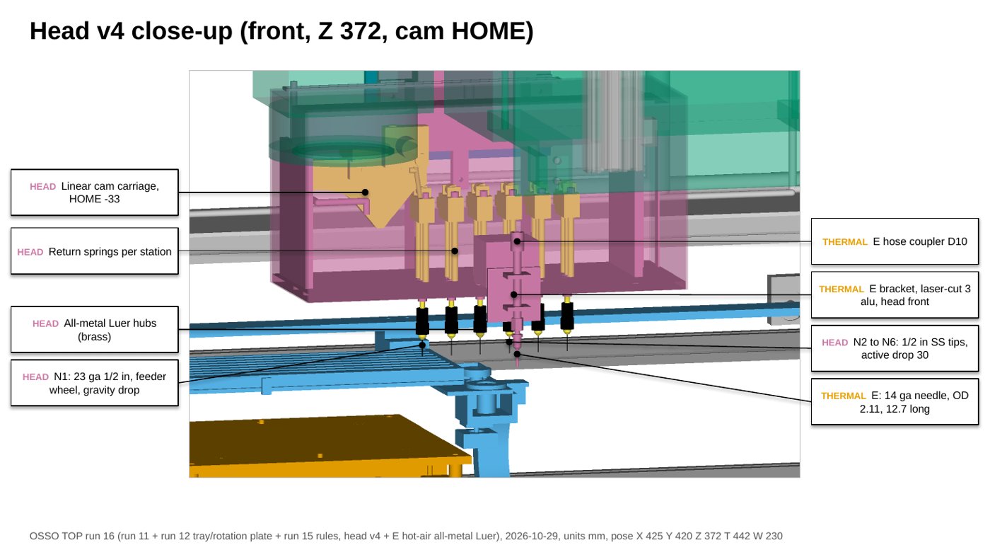
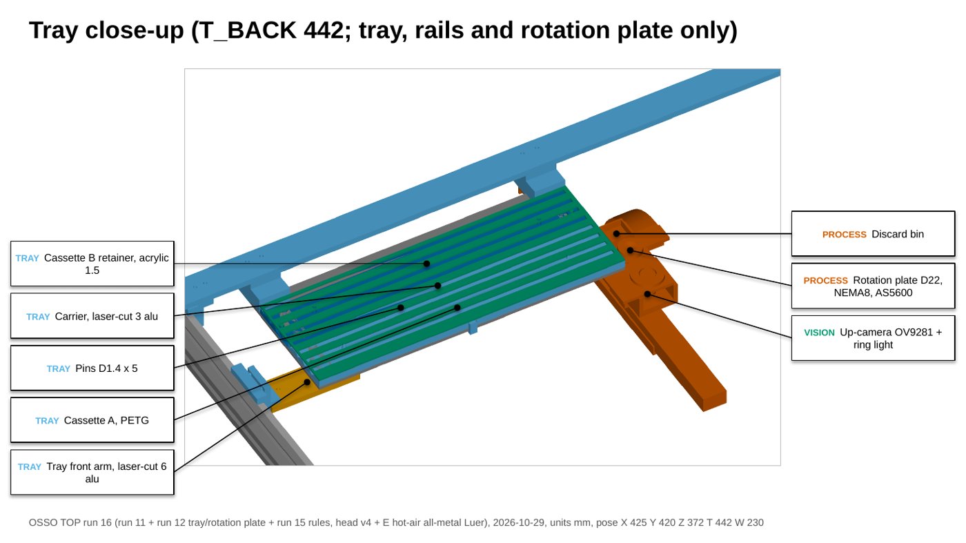
Run 16 (Oct 29, 2026) puts head v4 on the bench-top run 11 machine and brings back hot air: the hot-air (E) nozzle sits on the head-front bracket.
What changed in run 16
- Head v4. All six stations use all-metal 1/2 in Luer-lock tips (metal hub, 304 stainless shaft) on a 4.0 x 0.5 mm stainless tube, 25 ga on N2 to N6 and 23 ga on N1. Plastic hubs are not used because of reflow heat.
- N1 = ball drop only. N1 never picks; the solder ball falls by gravity through the tube and tip, with no air puff.
- Hot air (E) on the head-front bracket (approved), with a stainless 14 ga 1/2 in metal Luer nozzle.
- E-only Z soft limit 327.7 mm (approved), allowed only when the tray position T ≥ 462 mm. All other stations keep the Z ≥ 354.7 mm soft limit; needles go down only at T ≥ 462 mm.
- Checks: 622 parts; 28-pose clash check with 0 hits and a minimum gap of 2.0 mm; the motion animation passes the interlock scan with 0 violations and 0 clashes on 22 poses (minimum gap 3.17 mm). One known floating door clip carries over.
Machine motion
Renders
Views deck
Eight annotated views from the run 16 views deck (PPTX).
Tool head v4
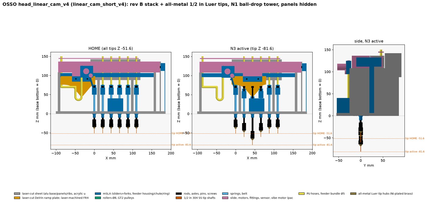
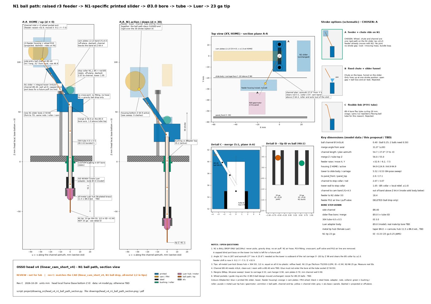
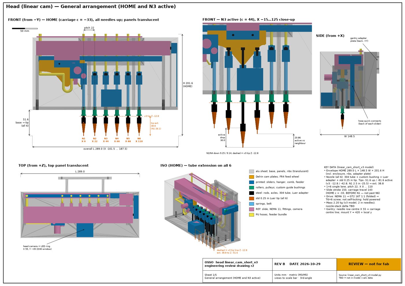
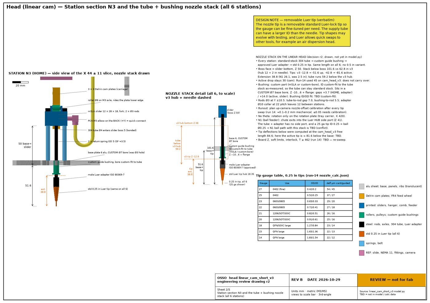
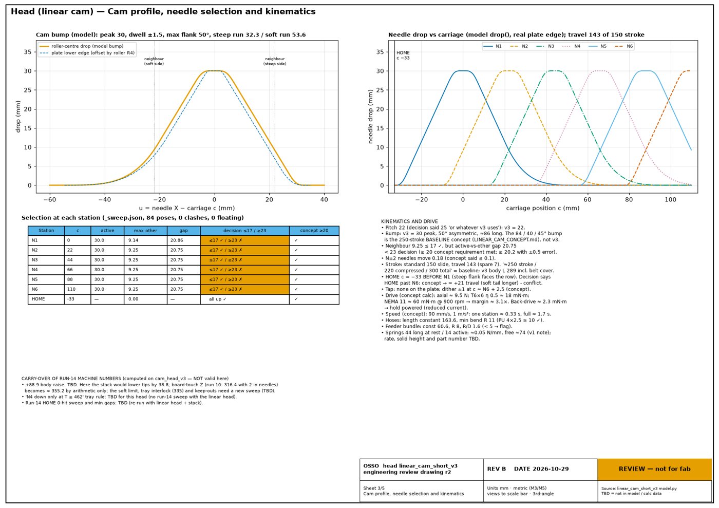
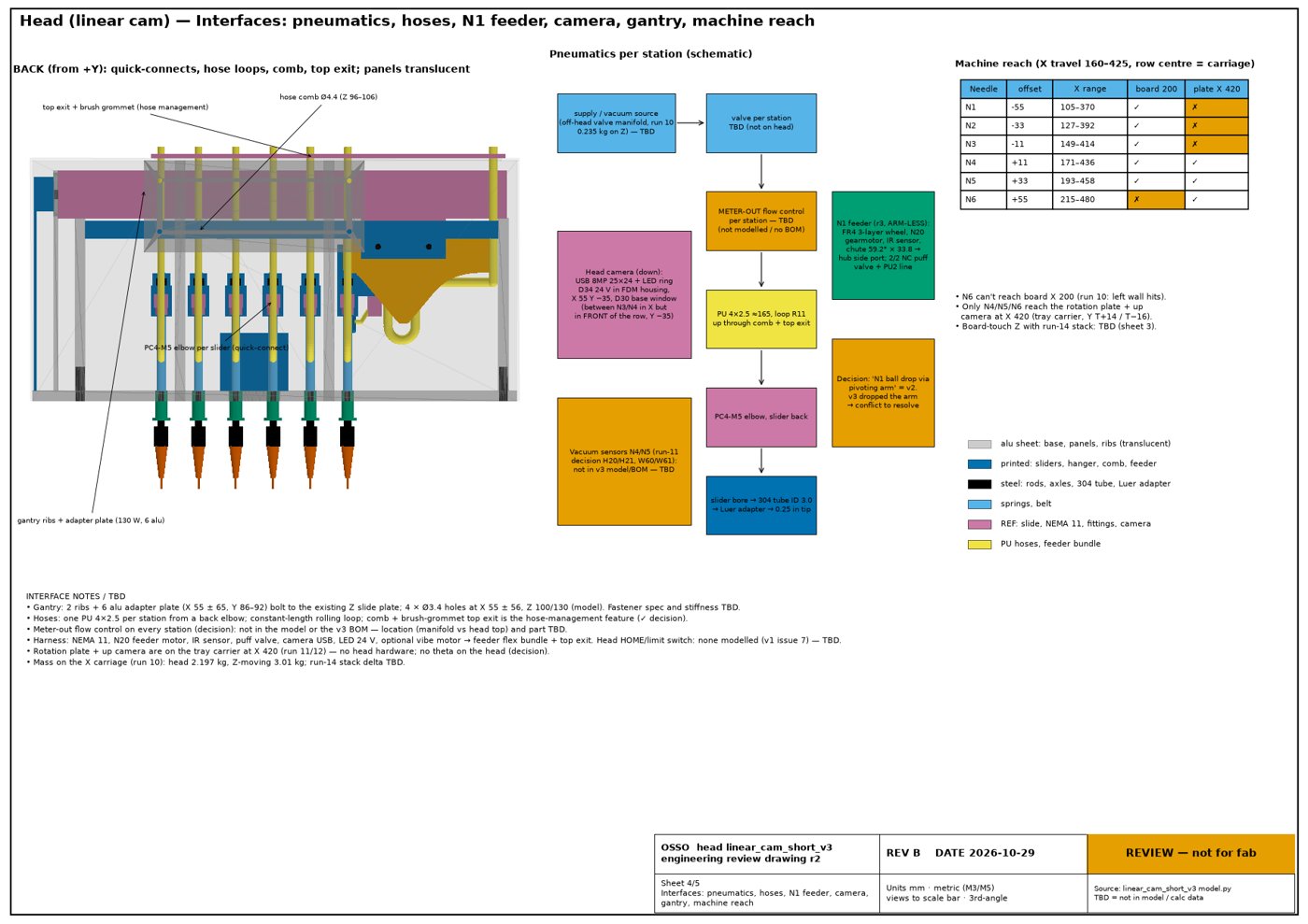
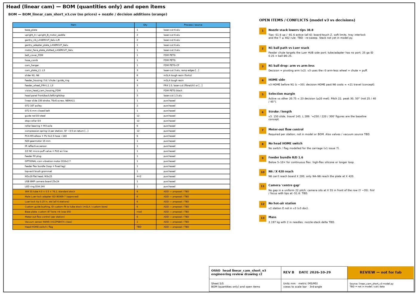
Solder-ball feeder r3
Downloads (run 16)
- osso_top.step (run 16, full top-level STEP) (zip)
- osso_top.glb (run 16) (zip)
- osso_top.usdz (run 16) (zip)
- head_linear_cam_v4.step
- head_linear_cam_v4.glb
- head_linear_cam_v4.usdz
- machine_motion.usdz (r2)
- linear_cam_short_v4_anim.usdz
- feeder_anim_r3.usdz
- osso_top_run16_views.pptx (views deck)
- head_linear_cam_review_r2.pdf
- head_v4_n1_ball_path_section.pdf
- README (run 16)
- Head v4 design notes
Run 11: bench-top unit and quick-connects
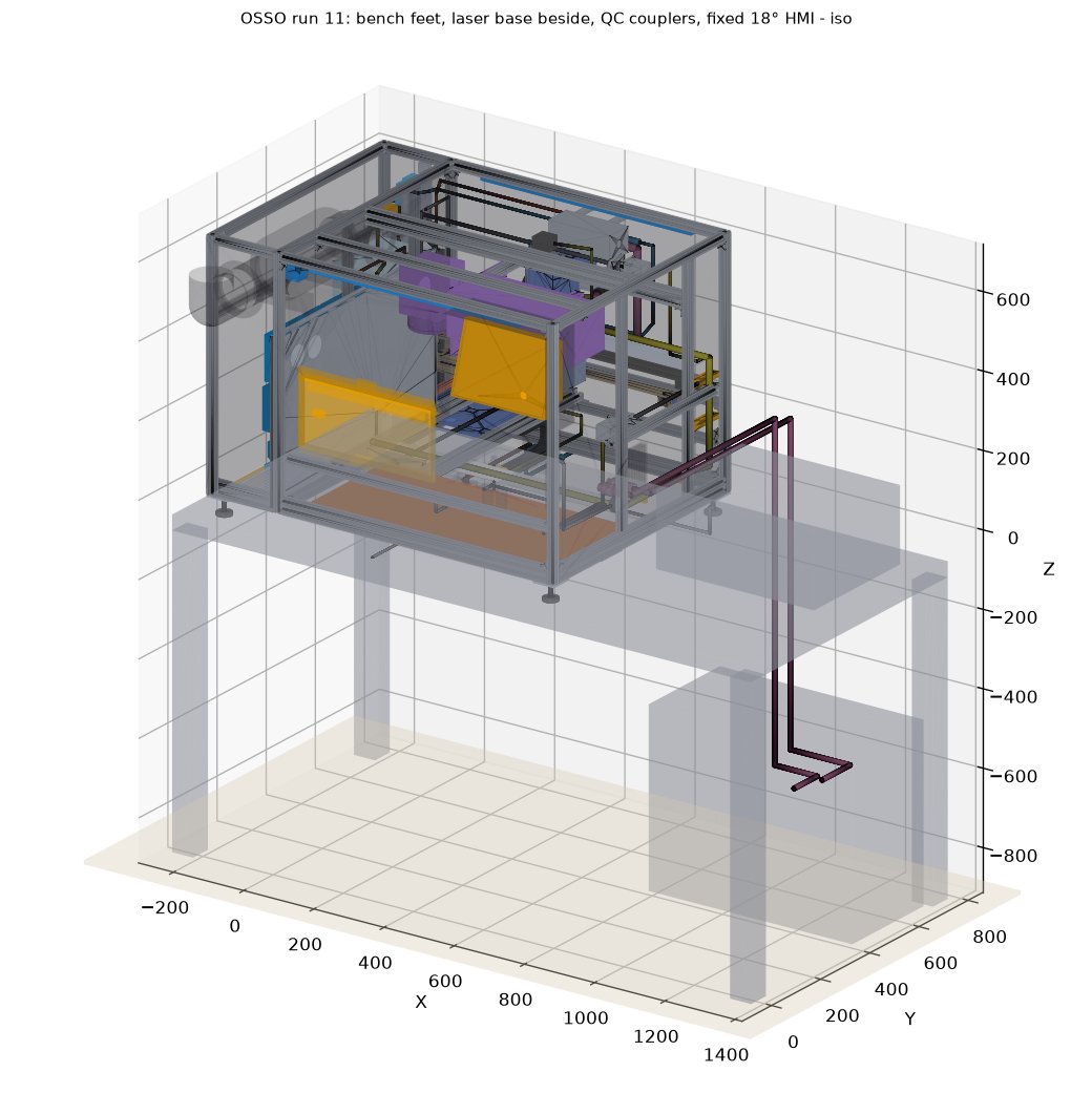
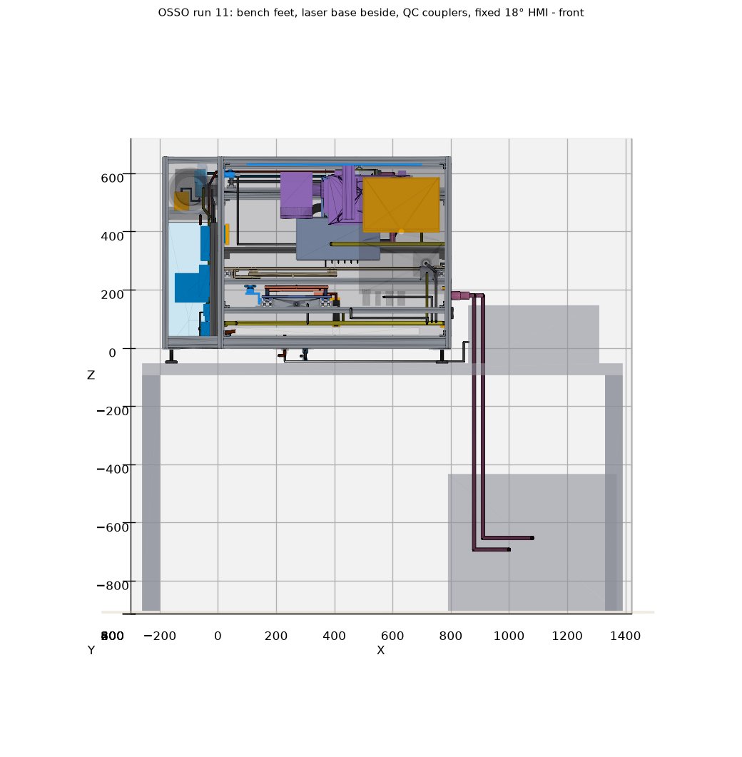
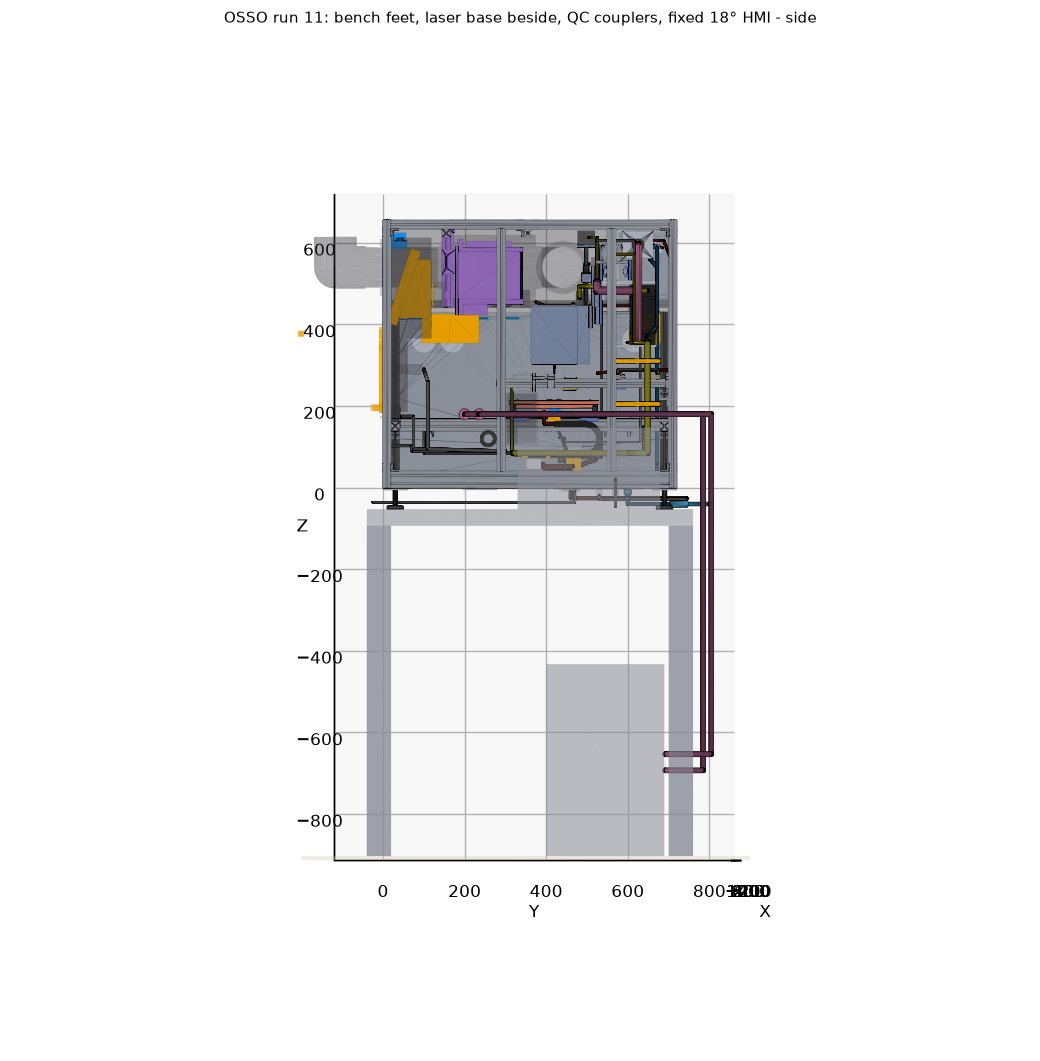
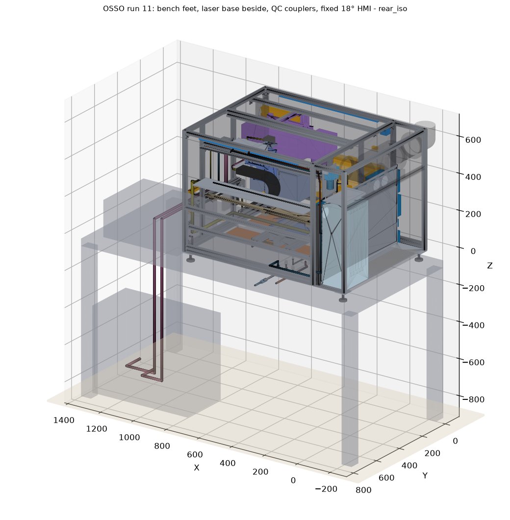
Run 16 keeps the run 11 bench-top frame, laser base beside the machine, quick-connects and fixed screen.
Quick-connect disconnect
Renders (run 11)