This snapshot is older than v21 and keeps notes and UI only; the large CAD, mesh and render files are no longer on this site.
New in this snapshot: 96 drawings, 0 STEP files, 0 documents/media.
2026-10-25 2:44 PM EDT: Real laser source measured
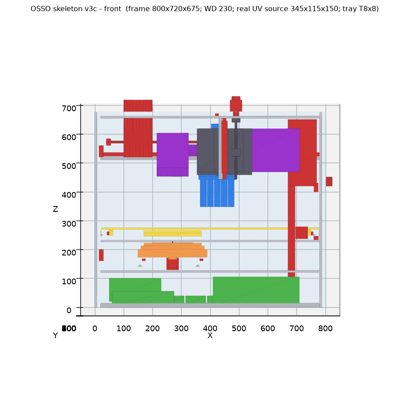
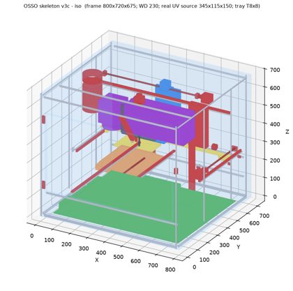
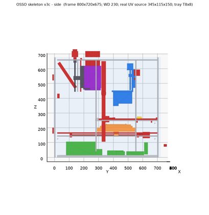
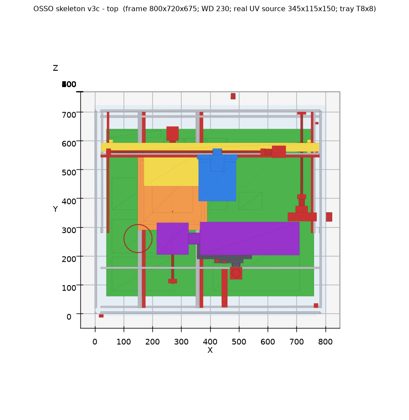
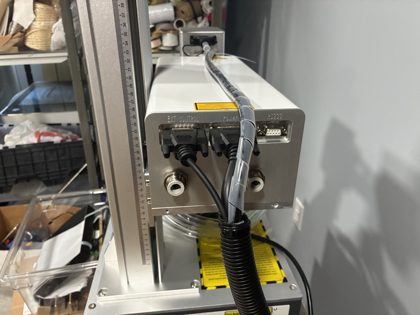
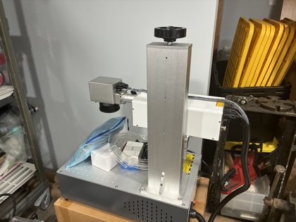
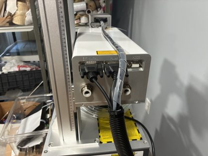
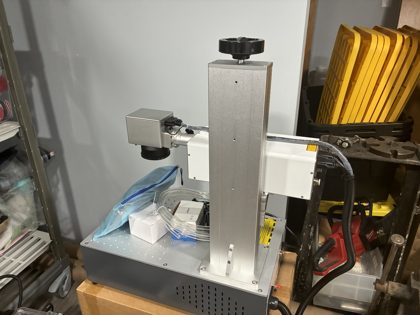
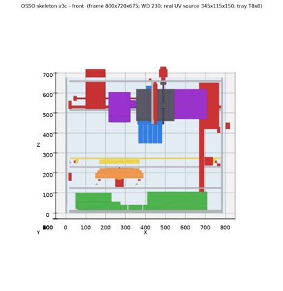
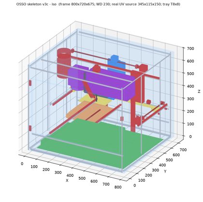
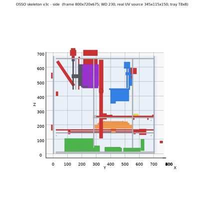
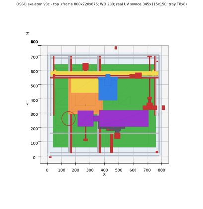
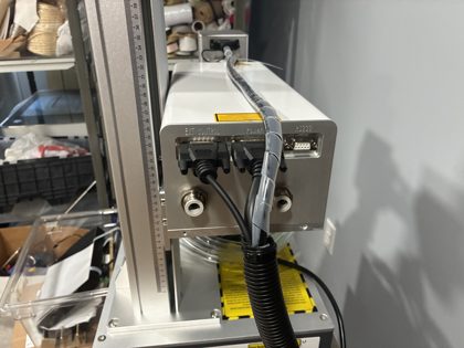
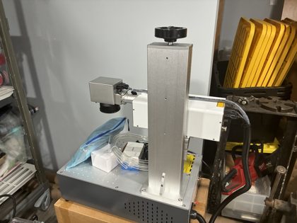
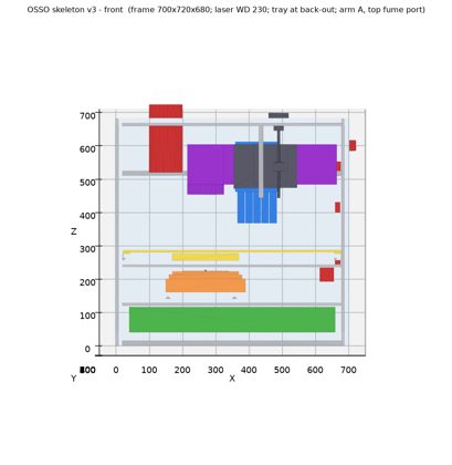
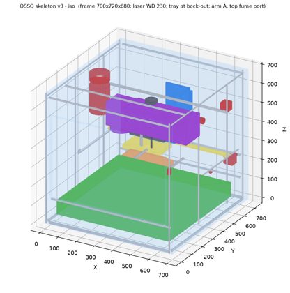
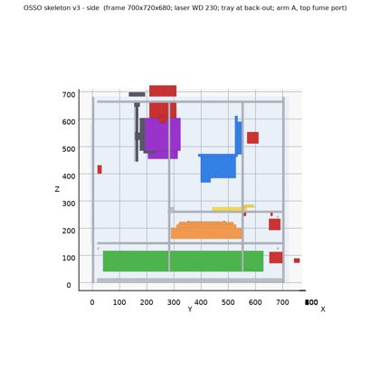
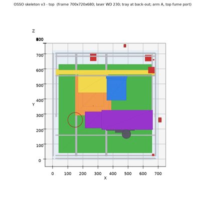
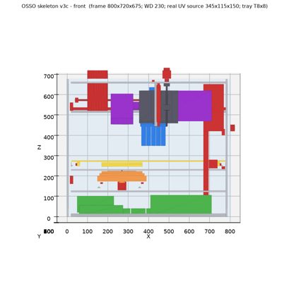
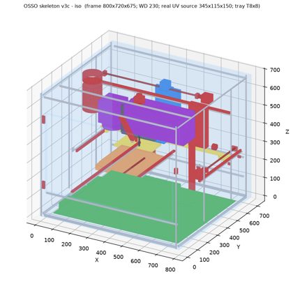
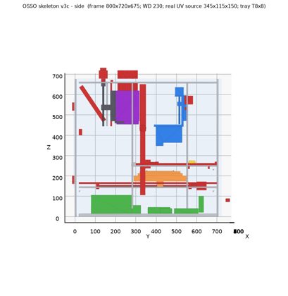
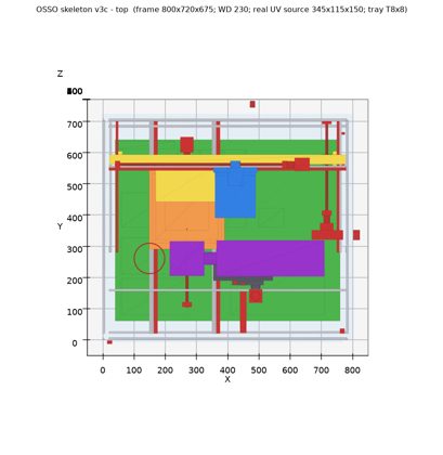
the designer's own unit (cad/integration/refs/laser_actual_*.jpg): the source (white box on the arm) is 115 x 150 x 345 mm plus connectors. Its rear face has EXT CONTROL (DB25), Power (DB), RS232 (DB9) and two coolant push-fittings, so it needs about 60 mm rear clearance for cable bend radius. The galvo is on the front end with the lens below. The power supply and controller sit in the grey base, so they go in the under-bed bay. Skeleton v3c will use the real source size.
- 2:45 PM: the designer: the laser's grey base (PSU and controller) stays outside next to the chiller. Its cables and coolant come through one rear pass-through. This replaces the earlier 'laser power in the bay' decision.
- 2:45 PM: Tray drive: T8x8 lead screw on MGN12 (same as X/Y).
- 2:52 PM: Focus guide: MGN12 on the column, no locks.
- 2:56 PM: Fume: plain top duct, no nozzle or hood.
- 2:56 PM: Fume fan: external, on the duct.
2026-10-25 3:08 PM EDT: Skeleton v3c built
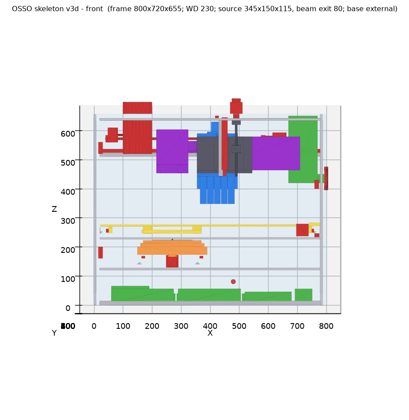
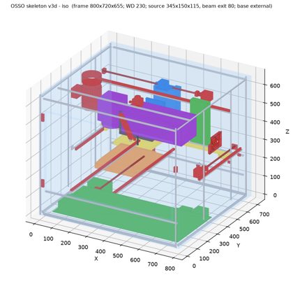
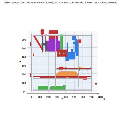
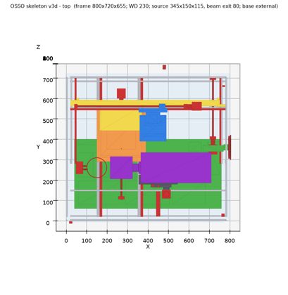
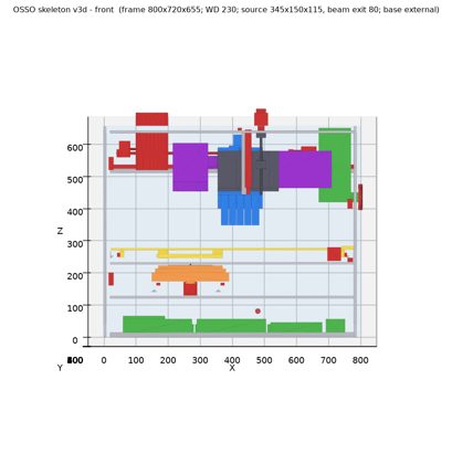
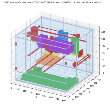
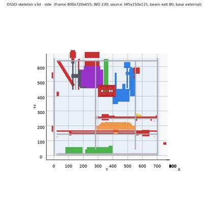
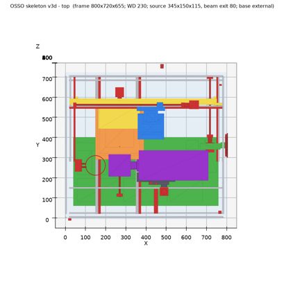
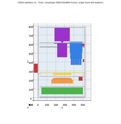
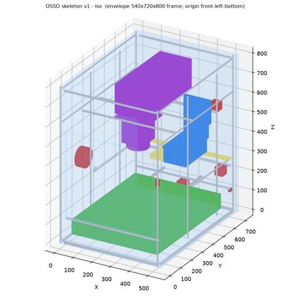
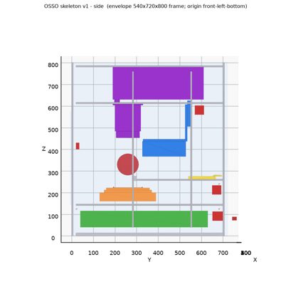
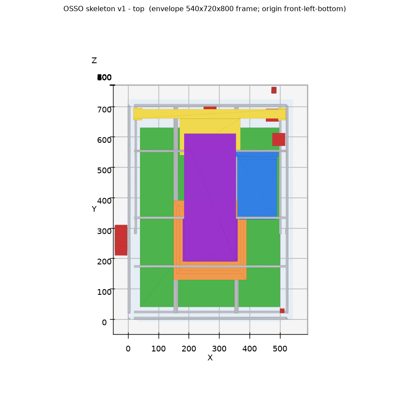
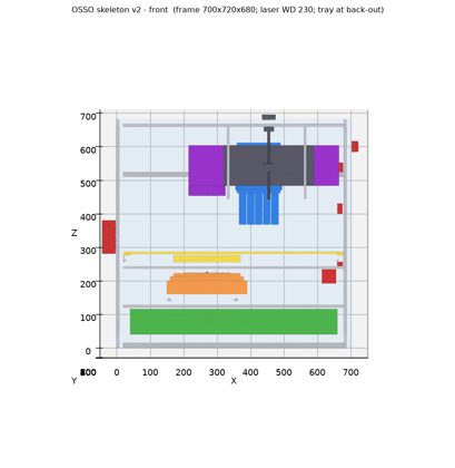
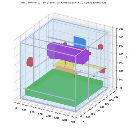
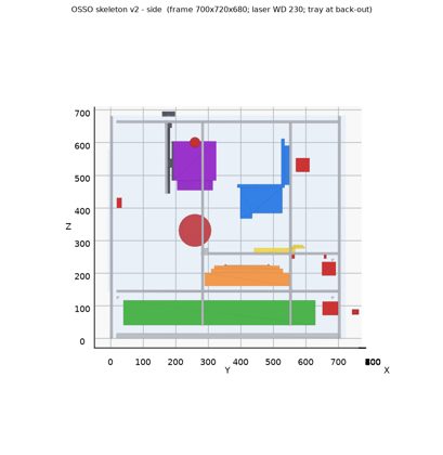
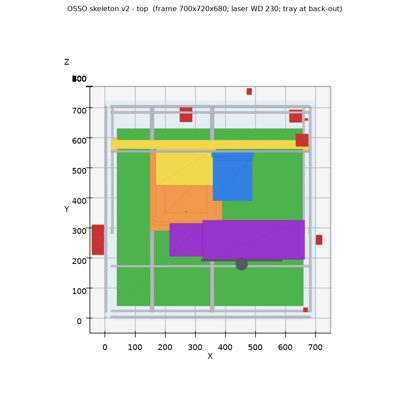
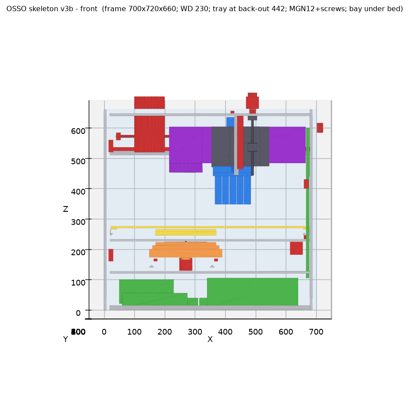
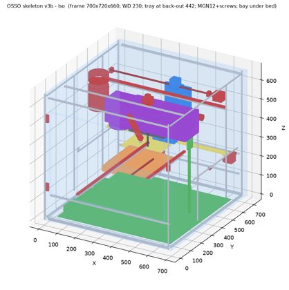
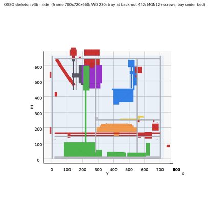
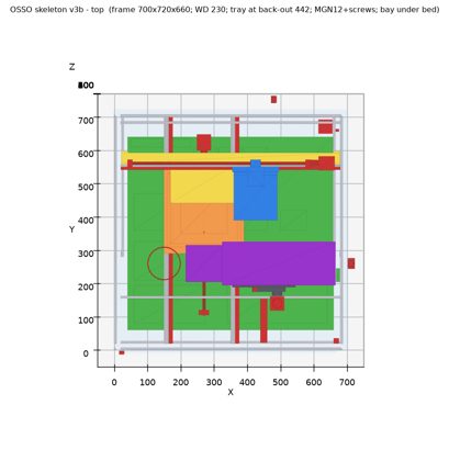
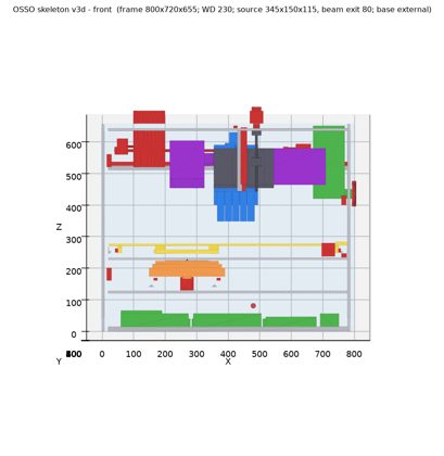
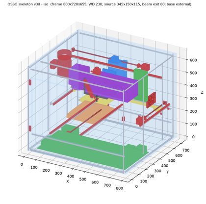
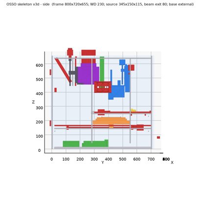
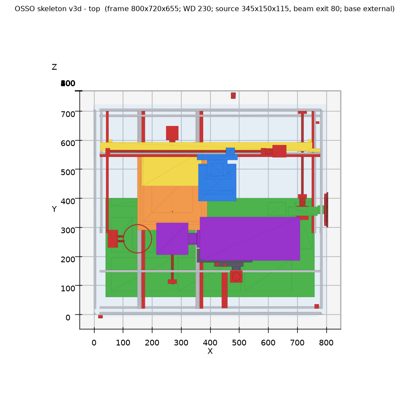
The real 345x115x150 source runs inline along +X with a 60 mm connector zone, and its service loop and riser are in. The tray has a T8x8 screw on MGN12. The focus guide is two MGN12H carriages on the column. The fume extraction is a plain top duct with an external fan. The frame grows to 800W x 720D x 675H (+100 W, +15 H), and the door is 740 wide. Error: the bay still holds the laser PSU placeholder even though the designer moved it outside; fix it in the next revision. Open: whether the beam is at mid-height of the source box (Q18). TODO items 46-47 were added.
- 3:08 PM: the designer accepted the 800 mm frame width.
- 3:11 PM: the designer will measure the beam exit height on the source; mid-height is the placeholder. Started v3d: laser PSU removed from the bay, laser cables through one pass-through.
- 3:12 PM: the designer measured the beam exit: 60 mm OD flange, centered 80 mm above the source bottom (115 mm side vertical). Applied in v3d.
- 3:14 PM: the designer: the machine sits on a bench with its longest side left to right. Rule: depth <= width.
- 3:21 PM: Skeleton v3d built. Frame 800x720x655 (-20 H). Bay 720x340x70. Beam exit at 80 mm. Single 50 mm gland on the right panel. Collisions: only the expected tray-row-8 vs beam cases. Open: whether the DB25 backshell fits through the gland.
- 3:29 PM: the designer chose a larger right-panel cutout with a bolted cover plate for the laser pass-through (the DB25 passes with its connector on). Being applied in v3d.
- 3:30 PM: the designer set the custom-part fabrication methods: FDM, mSLA, laser-cut sheet.
- 3:38 PM: v3d pass-through done: 90x50 right-panel cutout, split 3 mm black acrylic plate, FDM PETG clamp frame, 6x M3. Fab-method tags added.
- 3:54 PM: Decisions: tray-vs-beam interlock is sensors and firmware only (Q5 closed). Exhaust interlock is a real airflow sensor in the duct. Y stays T8x8 (default, card skipped). Started real CAD: Frame & Motion.
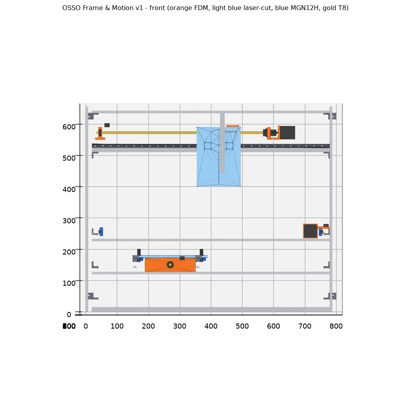
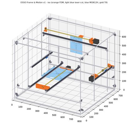
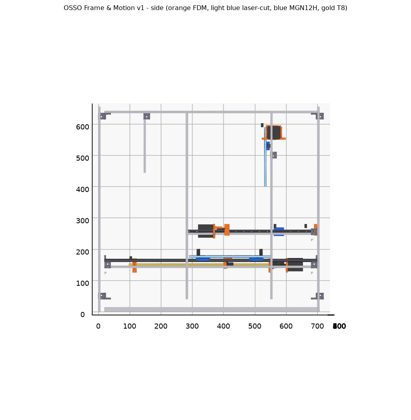
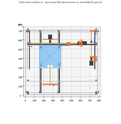
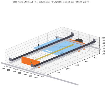
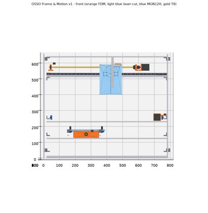
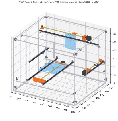
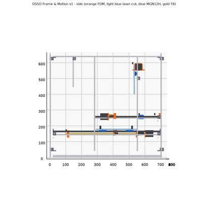
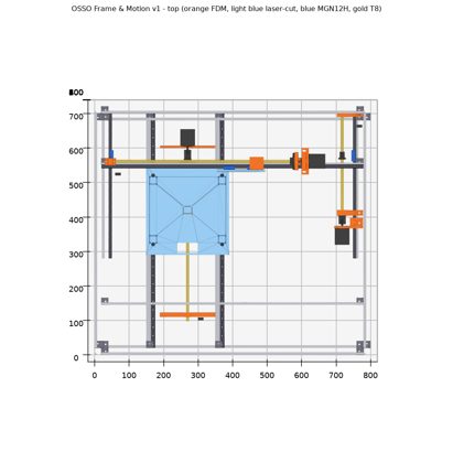
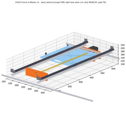
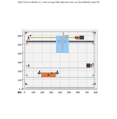
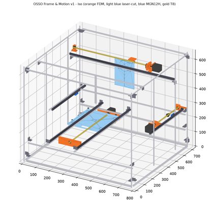
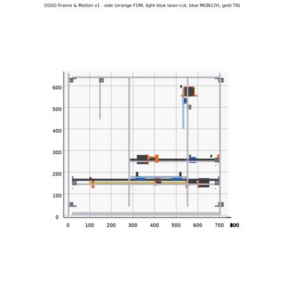
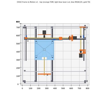
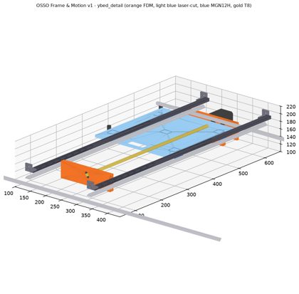
- 4:05 PM: Frame & Motion CAD v1 built (109 bodies, BOM 50 lines, 35 assembly steps, cut list). Torque safety factors 4.7-6.1. Differential-pressure airflow switch added to the duct. Open: head Z stack ~17 mm clash with the real X carriage; the 6 mm aluminium plates need an outside cutting service.
- 4:08 PM: the designer: shorten the head plate 17 mm at the rear and keep the needle line at Y 420. Started Head CAD.
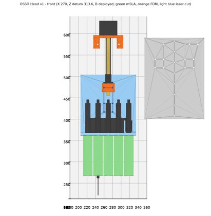
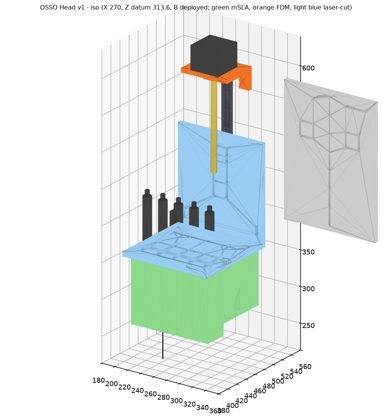
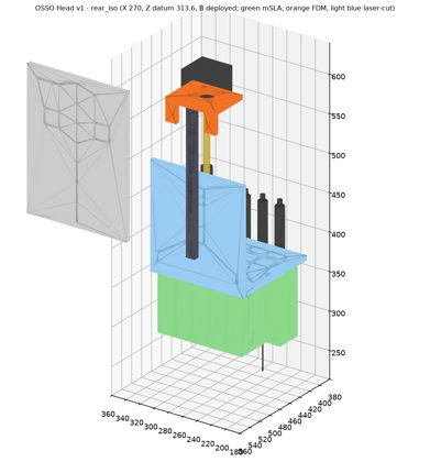
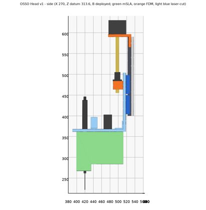
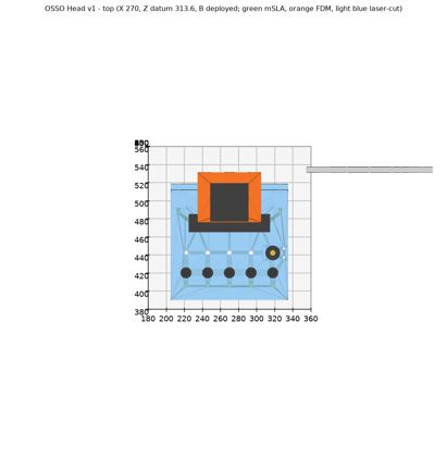
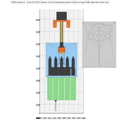
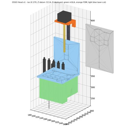
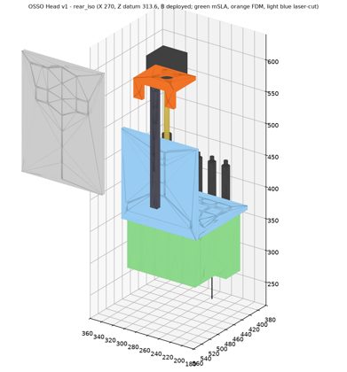
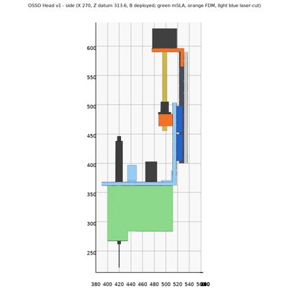
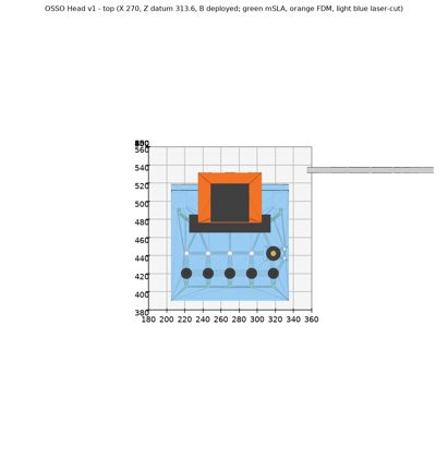
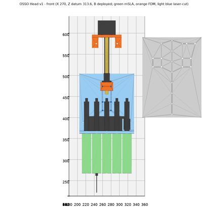
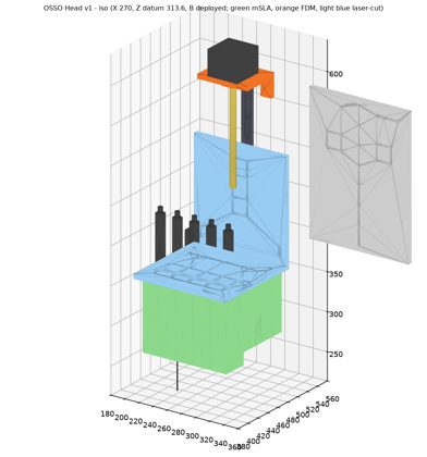
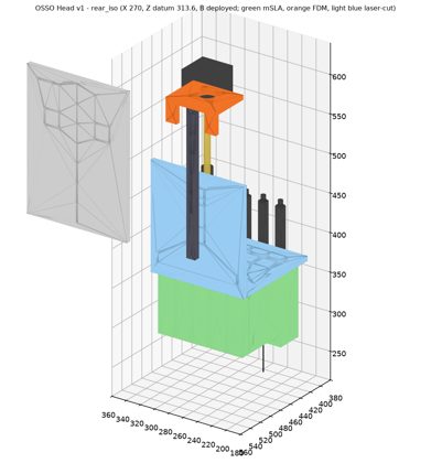
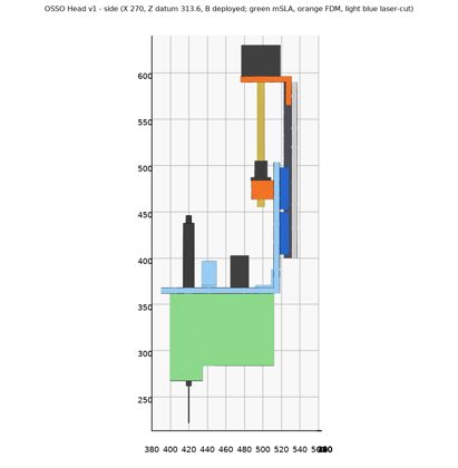
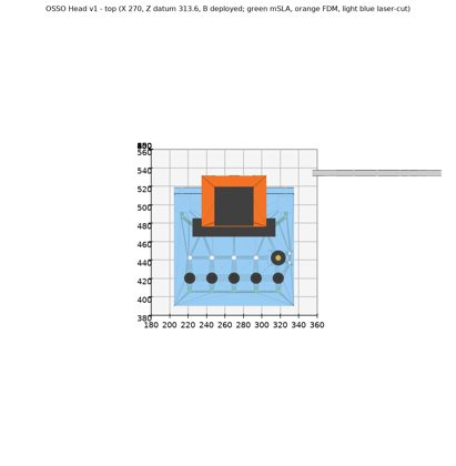
- 4:17 PM: Head CAD v1 built (52 bodies, BOM 30 lines, 15 steps). Head 2.88 kg; X axis safety factor 4.7. Head plate cut 17 mm; collisions clean. Open: actuator type, valve location, Z stiffness, hollow housings, hot-air resin/heater.
- 4:18 PM: the designer: station actuators are spring-return pen air cylinders.
- 4:19 PM: Head decisions: pen cylinders; valves on the head; second Z block; hollow ribbed mSLA housings; hot-air heater in the bay, piped up. Applying in head v1b.
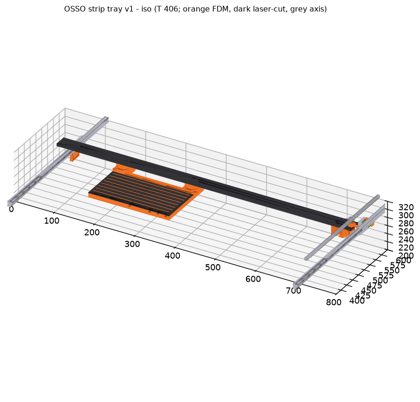
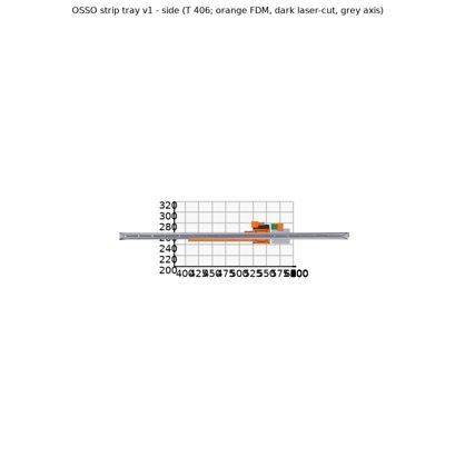
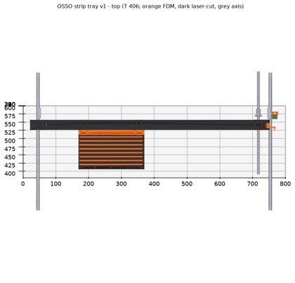
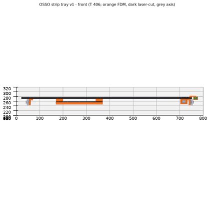
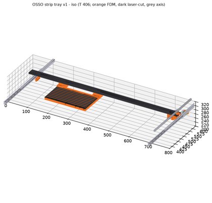
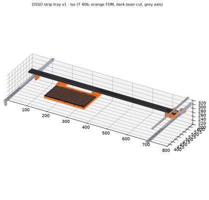
- 4:20 PM: the designer: storage is just the 8-row strip tray for now. Real tray CAD queued after head v1b.
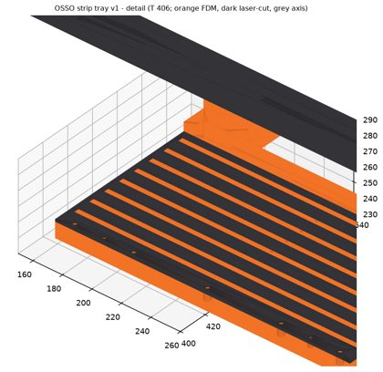
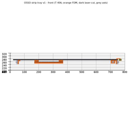
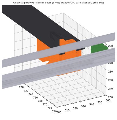
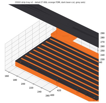
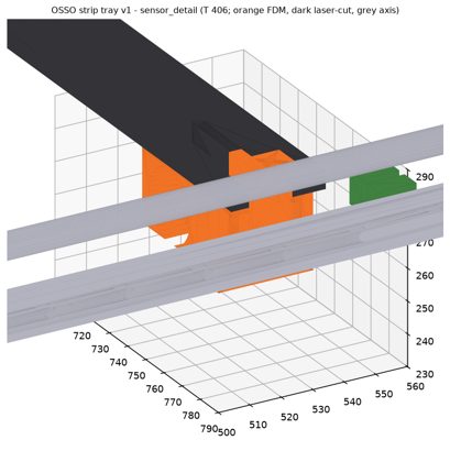
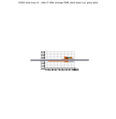
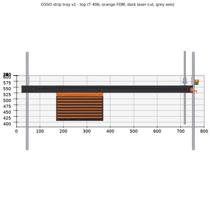
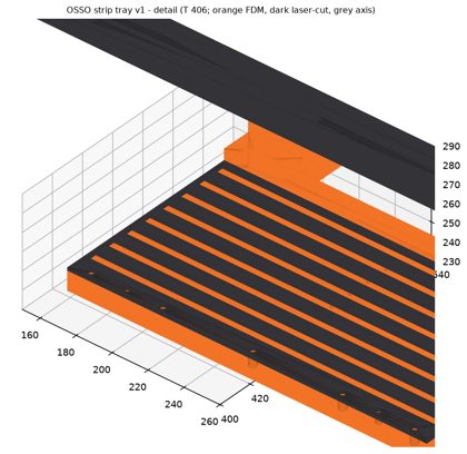
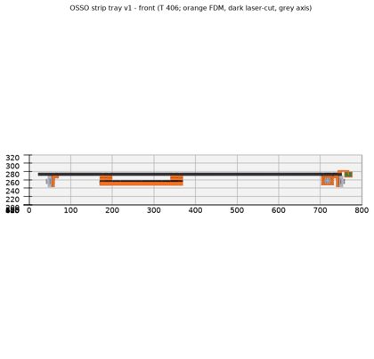
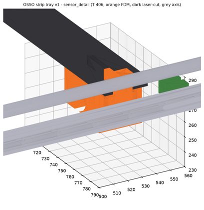
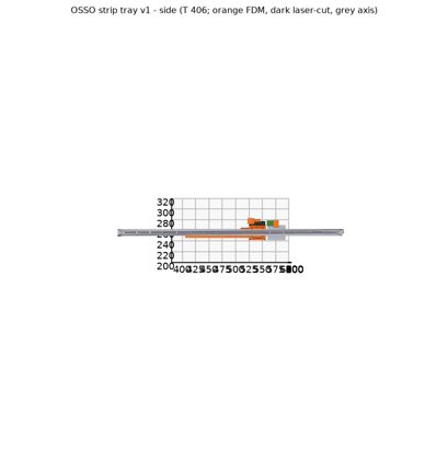
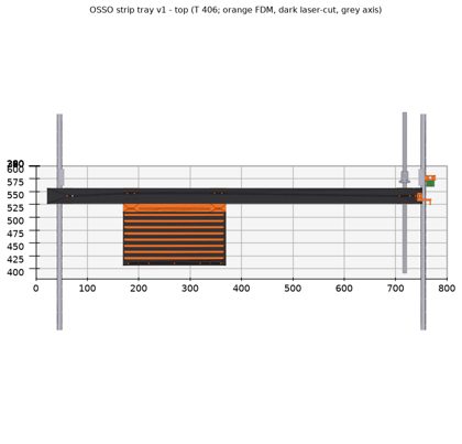
- 4:35 PM: Tray CAD v1 built (384 parts, 8 lanes, slot optical sensors, 0.81 kg, safety factor 6.0). The head v1b decisions weren't applied; re-dispatched.
- 4:46 PM: the designer: add sprocket pins to each tray lane for exact indexing. Cover tape is peeled before loading.
- 4:50 PM: Head v1b applied: 2 Z blocks, hollow housings (0.50 kg for five), heater in the bay with a 1.8 m hose and PEEK nozzle sleeve; housing E in high-temp resin. Head 2.56 kg, X safety factor 4.8. Tray sprocket pins (24x 1.4 mm); pocket positions fixed, no teaching needed. Collisions clean.
- 4:50 PM: Snap v18