← v10 v12 →
v11: Laser tech sheet, PnP machine/head drawings and decisions, Neptune 4 bed layout
Frozen Wed Oct 21, 2026, 9:29 AM ET · 7 files · folder: versions/v11_2026-10-21/
This snapshot is older than v21 and keeps notes and UI only; the large CAD, mesh and render files are no longer on this site.
What changed
New in this snapshot: 5 drawings, 0 STEP files, 0 documents/media.
Key decisions
Drawings new in v11
PDF
2026_10_21_grid_copper.svgPDF
2026_10_21_grid_mask.svgPDF
2026_10_21_resolution_pattern.svg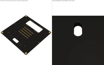
2026_10_21_OSSO_blank_v3b_preview_iso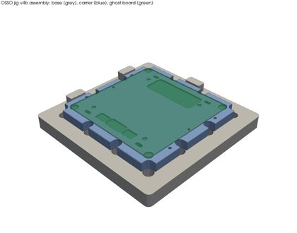
2026_10_21_preview_assembly_iso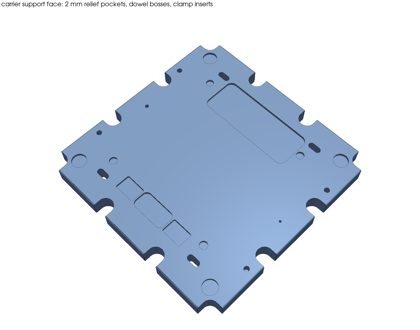
2026_10_21_preview_carrier_top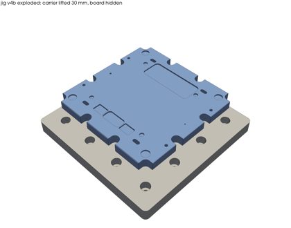
2026_10_21_preview_exploded_iso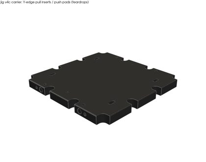
2026_10_21_preview_carrier_edge_iso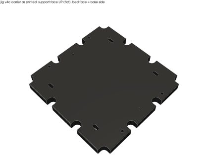
2026_10_21_preview_carrier_faceup_iso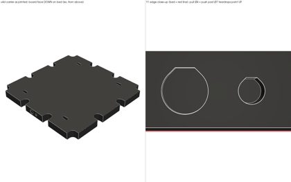
2026_10_21_preview_carrier_print_orientation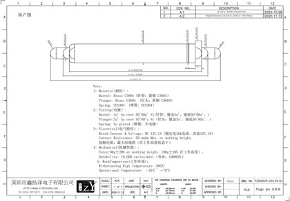
2026_10_21_YZD0029-20135-01_datasheet_drawing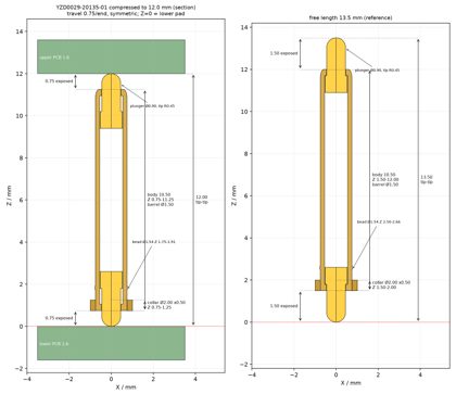
2026_10_21_YZD0029-20135-01_preview_12mm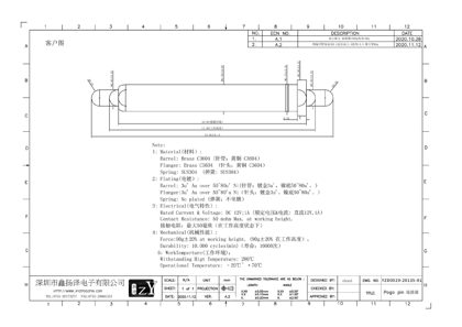
2026_10_21_datasheet_page3_200dpi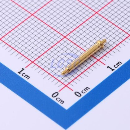
2026_10_21_lcsc_photo_front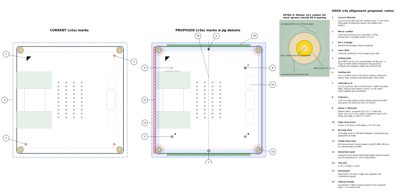
2026_10_21_align_proposal_v3a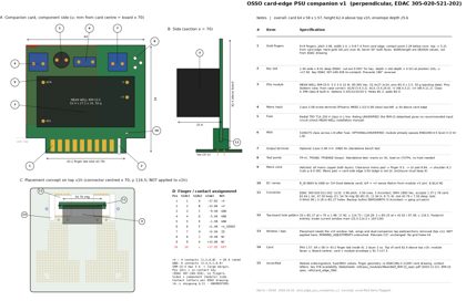
2026_10_21_card_edge_psu_companion_v1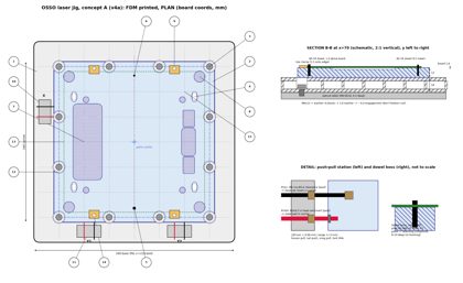
2026_10_21_jig_v4a_p1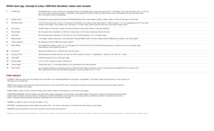
2026_10_21_jig_v4a_p2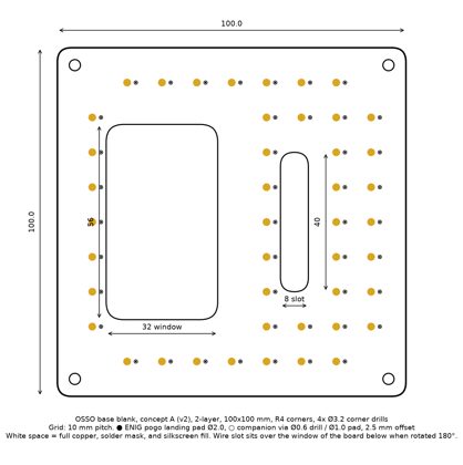
2026_10_21_osso_base_v2a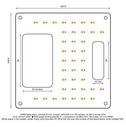
2026_10_21_osso_base_v2b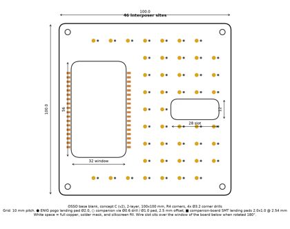
2026_10_21_osso_base_v2c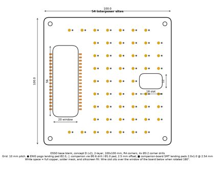
2026_10_21_osso_base_v2d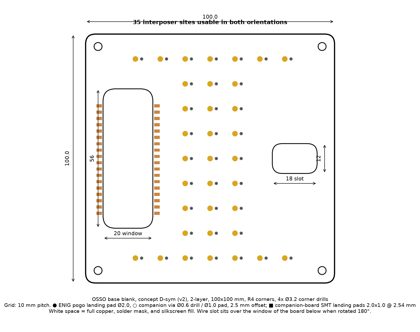
2026_10_21_osso_base_v2d_sym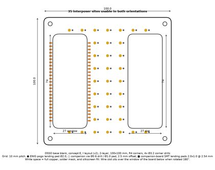
2026_10_21_osso_base_v2e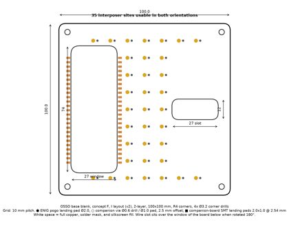
2026_10_21_osso_base_v2f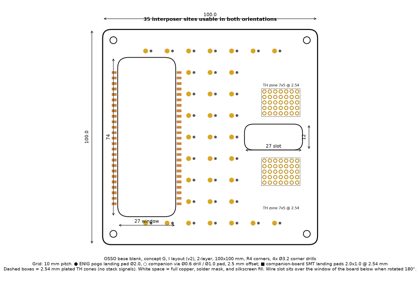
2026_10_21_osso_base_v2g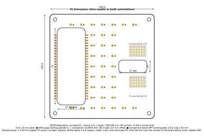
2026_10_21_osso_base_v2g2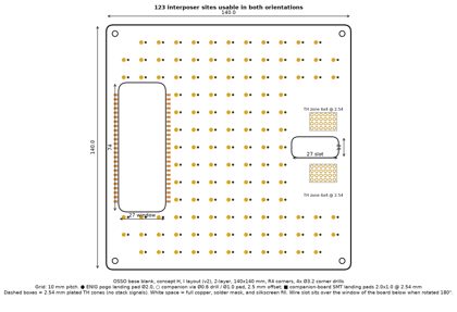
2026_10_21_osso_base_v2h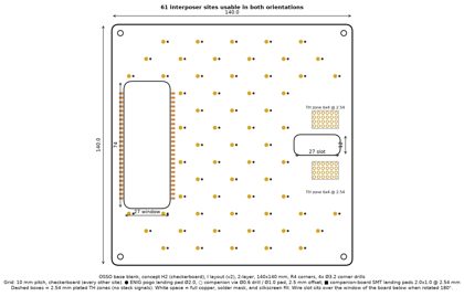
2026_10_21_osso_base_v2h2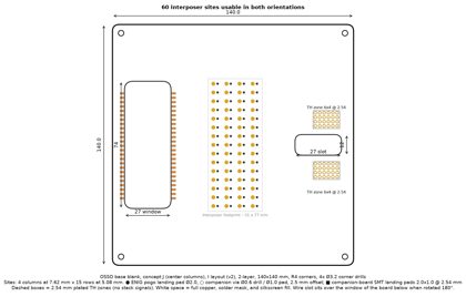
2026_10_21_osso_base_v2j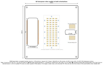
2026_10_21_osso_base_v2j2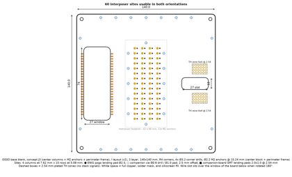
2026_10_21_osso_base_v2j3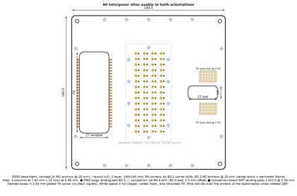
2026_10_21_osso_base_v2j4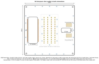
2026_10_21_osso_base_v2k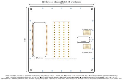
2026_10_21_osso_base_v2k2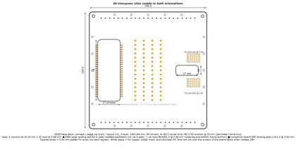
2026_10_21_osso_base_v2l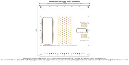
2026_10_21_osso_base_v2l_a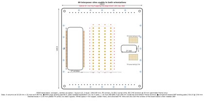
2026_10_21_osso_base_v2l_b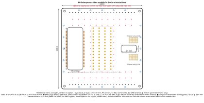
2026_10_21_osso_base_v2l_c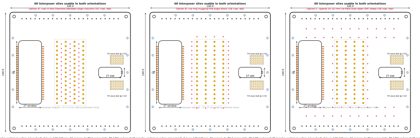
2026_10_21_osso_base_v2l_options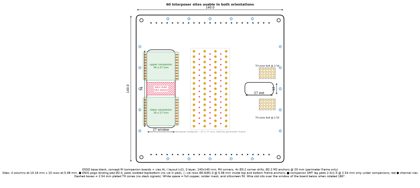
2026_10_21_osso_base_v2m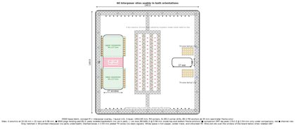
2026_10_21_osso_base_v2m_interposer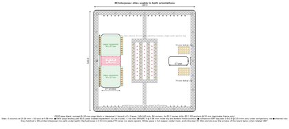
2026_10_21_osso_base_v2n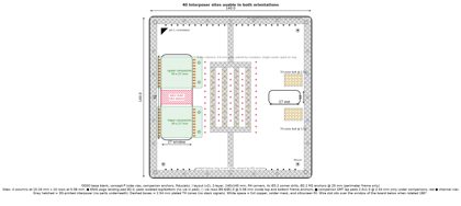
2026_10_21_osso_base_v2p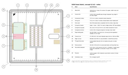
2026_10_21_osso_base_v2q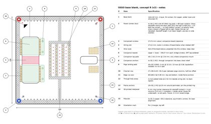
2026_10_21_osso_base_v2r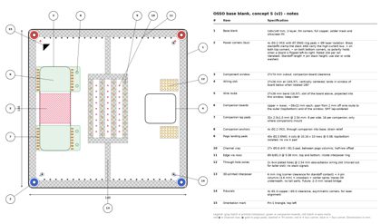
2026_10_21_osso_base_v2s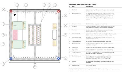
2026_10_21_osso_base_v2t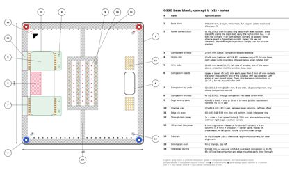
2026_10_21_osso_base_v2u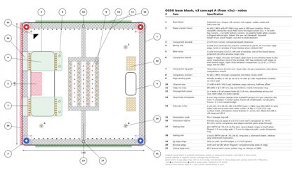
2026_10_21_osso_base_v3a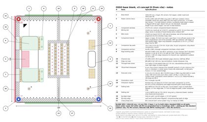
2026_10_21_osso_base_v3b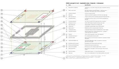
2026_10_21_osso_exploded_v2u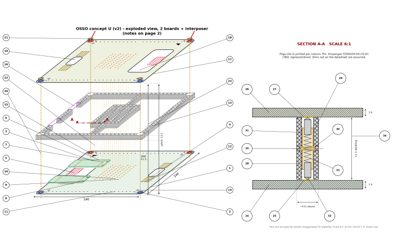
2026_10_21_osso_exploded_v2v_p1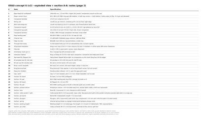
2026_10_21_osso_exploded_v2v_p2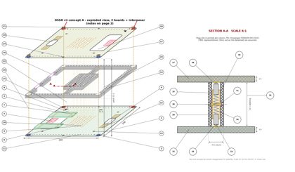
2026_10_21_osso_exploded_v3a_p1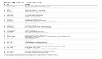
2026_10_21_osso_exploded_v3a_p2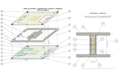
2026_10_21_osso_exploded_v3b_p1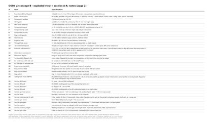
2026_10_21_osso_exploded_v3b_p2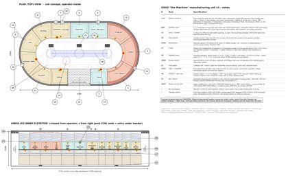
2026_10_21_osso_machine_cell_v1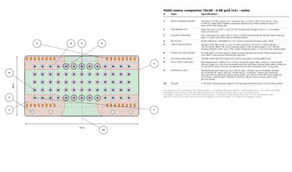
2026_10_21_osso_mains_companion_508_v1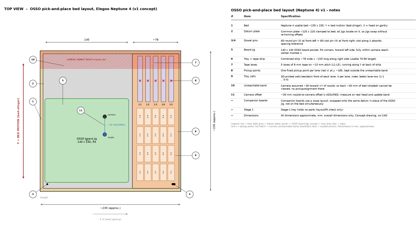
2026_10_21_osso_pnp_bed_n4_v1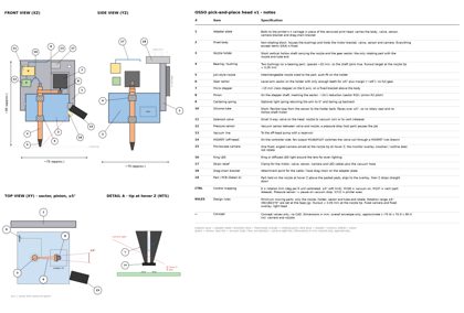
2026_10_21_osso_pnp_head_v1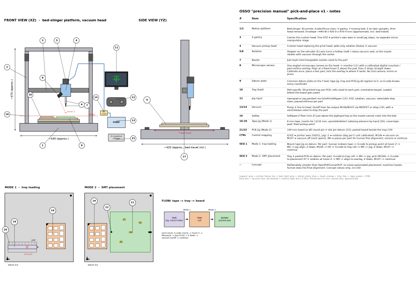
2026_10_21_osso_pnp_machine_v1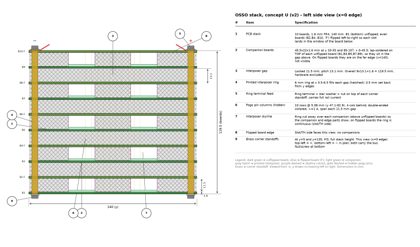
2026_10_21_osso_stack_side_v2u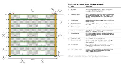
2026_10_21_osso_stack_side_v3a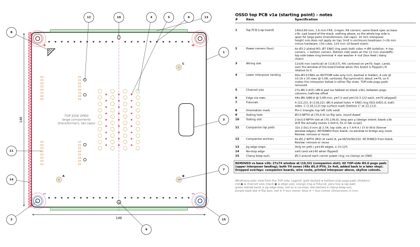
2026_10_21_osso_top_v1a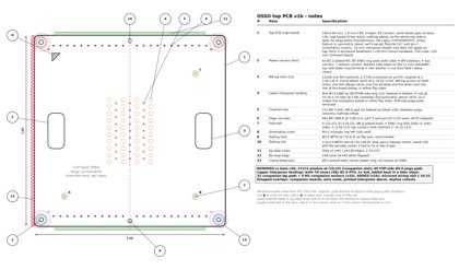
2026_10_21_osso_top_v1b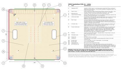
2026_10_21_osso_top_v1c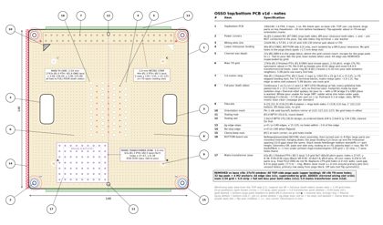
2026_10_21_osso_top_v1d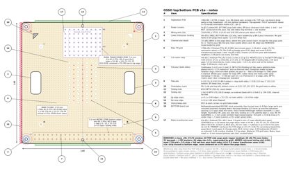
2026_10_21_osso_top_v1e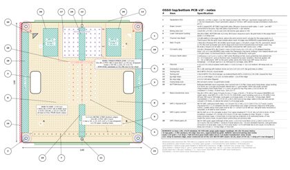
2026_10_21_osso_top_v1f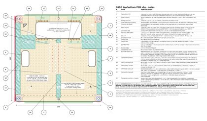
2026_10_21_osso_top_v1g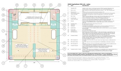
2026_10_21_osso_top_v1h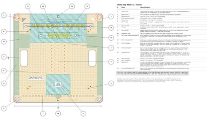
2026_10_21_osso_top_v1i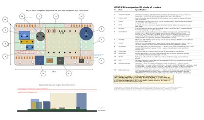
2026_10_21_psu_companion_fit_v1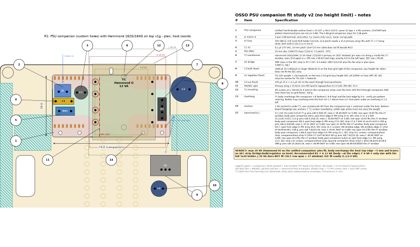
2026_10_21_psu_companion_fit_v2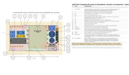
2026_10_21_psu_companion_fit_v3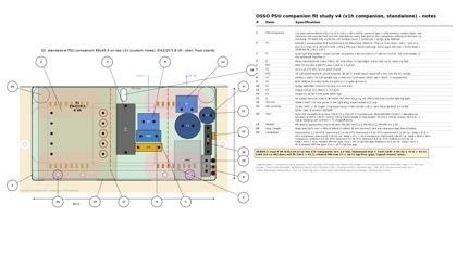
2026_10_21_psu_companion_fit_v4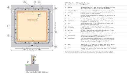
2026_10_21_stencil_frame_v1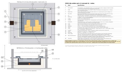
2026_10_21_wave_pot_v1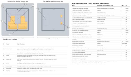
2026_10_21_wave_pot_v1_p2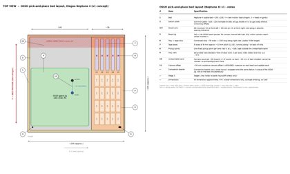
osso_pnp_bed_n4_v1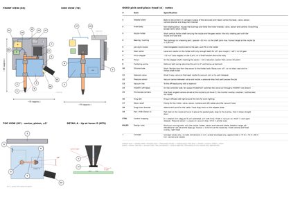
osso_pnp_head_v1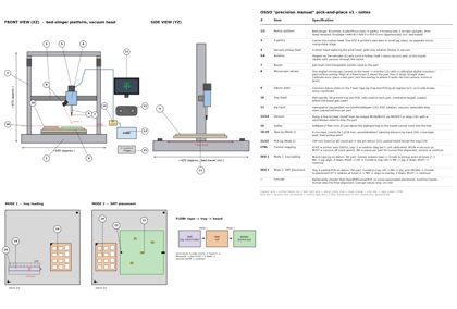
osso_pnp_machine_v1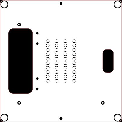
2026_10_21_GBL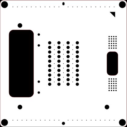
2026_10_21_GBO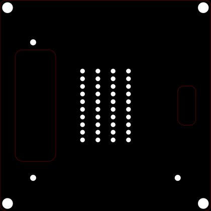
2026_10_21_GBS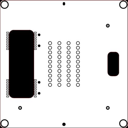
2026_10_21_GTL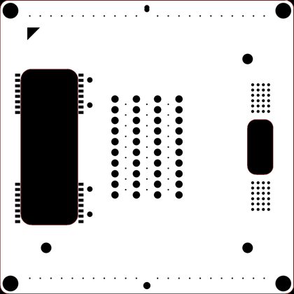
2026_10_21_GTO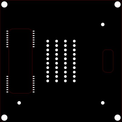
2026_10_21_GTS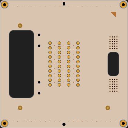
2026_10_21_composite_bot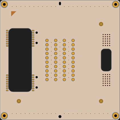
2026_10_21_composite_top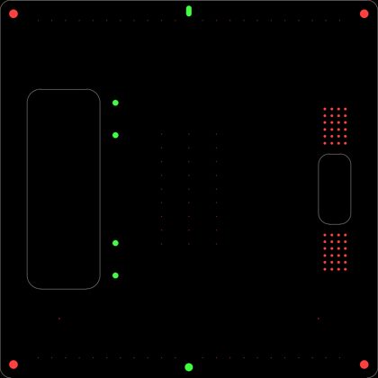
2026_10_21_drills_outline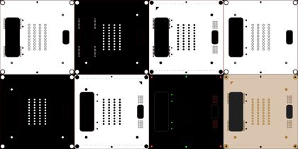
2026_10_21_sheet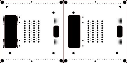
2026_10_21_silk_pair
2026_10_21_zoom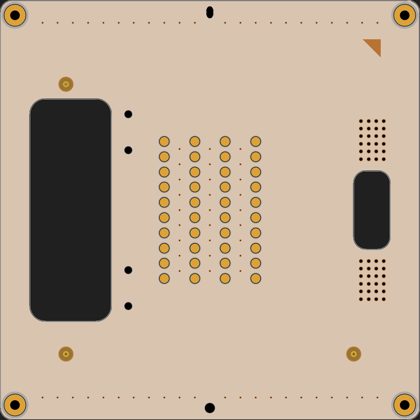
2026_10_21_OSSO_blank_v3b_preview_bot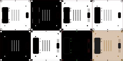
2026_10_21_OSSO_blank_v3b_preview_layers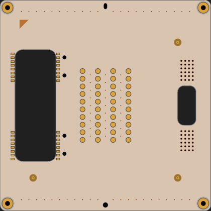
2026_10_21_OSSO_blank_v3b_preview_top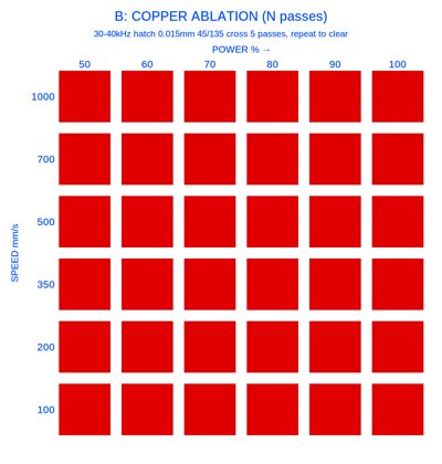
2026_10_21_grid_copper_preview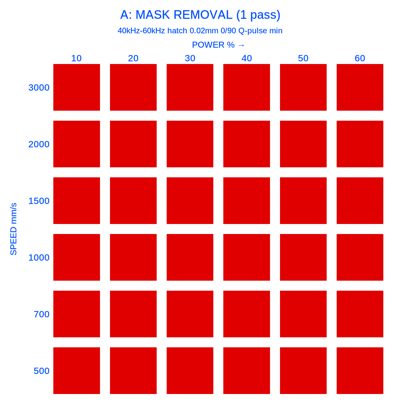
2026_10_21_grid_mask_preview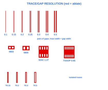
2026_10_21_resolution_pattern_preview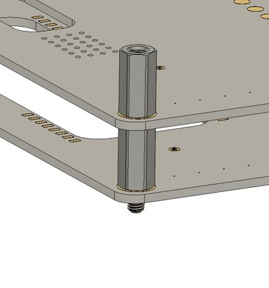
2026_10_21_designer_standoff_12mm_cad_2026-10-19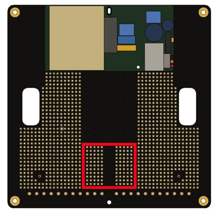
2026_10_21_2026-10-20_top_v1h_lower_center_SMT
2026_10_21_PI_film_0075_order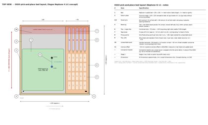
osso_pnp_bed_n4_v1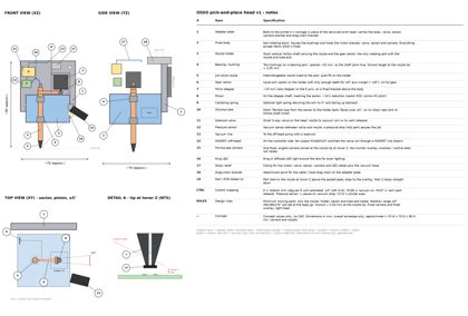
osso_pnp_head_v1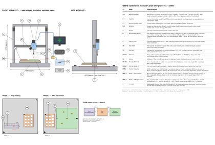
osso_pnp_machine_v1STEP files (0)
Documents & media
Journal entries in this version
2026-10-20 2:06 PM ET — Laser technical summary sheet
project/refs/laser/LASER_TECH_SHEET.md + laser_tech_sheet.pdf (2 pages): a technical summary of the 10W 355nm UV galvo (CRS-355-10 source, RC1001 Sino-Galvo, JCZ EzCad/LightBurn, water-cooled, 20–150 kHz, <15 ns at 40 kHz, 0–7000 mm/s, 150×150 and 300×300 fields). It includes tech data only; no commercial details. Neither document gives focal length, working distance, Z travel or M². Spot "0.4–0.7 mm" is flagged as doubtful, and 110 V/50 Hz vs the US plug is flagged as a conflict. The vendor originals are in project/refs/laser/source_private/, which build_site.py now excludes from the References page. The tech sheet is listed on the References page.
Also fixed in build_site.py: version_files() now skips site/ copies inside snapshots. The v10 snapshot contains site/, and its thumbnail names were nesting until the build failed with 'File name too long'. Nested thumbnails were removed. Build: 23 pages, check_links: 1502 links, 0 problems.
2026-10-20 2:24 PM ET — Decision: board goes in after the film cut
The stencil film is laser-cut with NO PCB in the jig. This avoids marking the board with the out-of-focus beam that passes through the cut openings, and avoids film debris landing on the pads. After the cut, with the frame still on its dowels, place the PCB on the lift carrier (lowered), clear any debris, then lift it to the film plane and print. Applies to stencil v2 and later. The stencil v2 drawing notes will be updated at the next regen.
2026-10-20 9:27 PM ET — Direction: "precision manual" placement of small parts (exploration, no models yet)
the designer's chosen next challenge is placing small parts simply and cheaply for hobbyists, without a robot at first, while still supporting small parts when those are the only ones available. His initial thoughts:
- It's remote controlled (a manipulator), so it doesn't depend on steady hands.
- Inspiration: "An Open Source Motorized XYZ Micro-Manipulator - Affordable sub µm Motion Control" (video). Could it be adapted for this?
- Part rotation has to be handled.
- A part tray set up ahead of time is accepted, and it may need its own tool or innovation.
- It should be simpler and more manual than OpenPnP and LumenPnP.
To be discussed Oct 21. Do not build models yet.
2026-10-21 8:15 AM ET — Decision: OSSO PnP architecture, G-code coarse moves with human fine control
- Platform: a "bed slinger" 3D printer motion system with the print head removed and replaced by a custom vacuum pickup head.
- Coarse moves (everything except the last few mm) are G-code, generated from the known placement coordinates on the PCB and the known coordinates of each part's position in the tray.
- Fine control happens on a movement actuator on the head, using jog commands: nudge X/Y/Z, rotation and vacuum on/off. The human runs these while watching a microscope camera on a monitor.
- This is deliberately different from OpenPnP/LumenPnP: no vision-automated placement; the machine does the travel and the human does the final alignment.
No models yet.
2026-10-21 8:16 AM ET — Decision: PnP fine motion
Fine XYZ moves use the printer's own axes in small jog steps. The custom head only needs to add rotation (theta) and the vacuum. No separate micro-manipulator stage for now.
2026-10-21 8:19 AM ET — Decision: PnP part tray
- A 3D-printed tray made for each specific PCB, with each cell sized to its component.
- The tray is loaded before the board gets paste, so every part is ready.
- The tray rides on the bed slinger beside the PCB and registers to the same datum, so the G-code can move automatically to each part's cell for pickup, then fine jog takes over.
2026-10-21 8:22 AM ET — Decision: PnP tray loading
Tray loading is a separate step done ahead of time on the same machine. The operator advances the part tape through a tape jig by hand to expose the next part. G-code moves the head to the tape pickup point, then to that part's tray cell. The human makes the final pick and drop, the same way as at placement.
2026-10-21 8:24 AM ET — Decision: PnP operator controls
The operator controls X, Y, Z, rotation and vacuum on/off. X/Y/Z use the printer's own axes. Rotation is driven by the extruder (E) axis and vacuum by the fan output (M106/M107), both triggered from G-code on the head.
2026-10-21 8:27 AM ET — Decision: PnP camera alignment
One angled microscope camera with a calibrated digital crosshair or part-outline overlay on the monitor. Alignment is judged at a fixed hover Z above the pad, then Z drops straight down. Calibrate once by placing a test part and locking the overlay to where it lands. No second camera, mirror or prism.
2026-10-21 8:30 AM ET — PnP machine concept drawing v1
project/drawing_src/osso_pnp_machine_v1.py → .png/.pdf (concept only, no CAD). Shows the "precision manual" pick-and-place built on a bed-slinger printer (Ender/Prusa class) in front (XZ) and side (YZ) views: X gantry, Y moving bed, Z uprights; custom vacuum head with E-axis rotation stepper, hollow shaft / rotary vacuum seal and Juki-style nozzle; one angled microscope camera feeding a monitor with a crosshair/outline overlay at a fixed hover Z; software Z floor; pump, line, MOSFET/relay + vent valve on M106/M107; gamepad/jog pendant via OctoPrint/Klipper. Bed-plan insets on the common datum plate: Mode 1 (tape jig 8 mm with 12/16 inserts, sprocket/detent index, cover-tape peel, pickup point + tray) and Mode 2 (tray + 140 mm PCB jig, Ø3 pin + slot pin). Flow strip tape → tray → board. Notes table: control mapping (E = rotation, M106/M107 = vacuum, M0 = pause per part) and both operation sequences. Overall dims only: envelope ~440×420×470 mm (approximate).
2026-10-21 8:33 AM ET — Decision: PnP chassis accuracy scope
The bed slinger does not need to be precise. The camera and operator absorb all slop, such as backlash, squareness and endstop error, when landing each part. The chassis only has to hold the part without dropping it, and travel without crashing into placed components or the tray walls: safe travel height, Z clearance and smooth motion. Priorities this sets: safe-Z travel moves, gentle acceleration, and secure vacuum hold during travel.
2026-10-21 8:34 AM ET — Confirmed: PnP chassis requirements
the designer confirmed all current chassis notes as requirements:
- safe-Z travel above the tallest part or tray wall
- vacuum hold check (pressure sensor that pauses on a drop)
- gentle Y acceleration
- dowel-located tray and board on a repeatable bed plate
- cable/hose management (drag chain or strain relief)
- e-stop
- even camera lighting
Precision homing and backlash fixes are not required; the camera and operator absorb the slop.
2026-10-21 8:39 AM ET — Decision: PnP rotation strategy
The camera is fixed and only the nozzle rotates. Rotation is limited to very small fine trims, within about ±5°. All 90°, 180° and 270° rotation happens at the tape jig: the operator feeds the tape into the jig at the right starting orientation, so each part goes into its tray cell already facing the way it will be placed. The overlay crosshair or outline never rotates, and the head stays light.
2026-10-21 8:40 AM ET — Decision: tray cells keep part rotation
Each tray cell is shaped and rotated to hold its part in the final placement orientation (set at the tape jig) and keep it there. Placement from the tray therefore needs only minor rotation correction (fine trim), the same as loading.
2026-10-21 8:43 AM ET — Decision: PnP nozzle rotation drive
Only the nozzle and a short flexible silicone tube rotate (±5°). There is no rotary seal and no hollow-shaft motor. The valve, sensor and camera stay fixed. The drive is a very small stepper (on the E axis) through a gear reduction, keeping moving parts to a minimum. The nozzle runs in a bearing or bushing so it spins true.
2026-10-21 8:44 AM ET — Decision: PnP rotation gear
The nozzle holder carries a lever-arm gear sector with only enough teeth to mesh with the stepper pinion over ±5° plus margin. No full gear.
2026-10-21 8:47 AM ET — PnP head concept drawing v1
project/drawing_src/osso_pnp_head_v1.py → .png/.pdf (concept only, no CAD). Shows only the pick-and-place head in front (XZ), side (YZ) and top (XY) views plus Detail A (nozzle tip with a part at hover Z above pasted pads). Adapter plate to the X carriage (print head removed); fixed body; Juki-style nozzle on a short hollow holder in two bushings (runout target < 0.05 mm); ~15 mm class E-axis stepper with a pinion meshing a lever-arm gear sector (teeth for ±5° plus margin, ~10:1, R20/R2); optional centering spring; short silicone tube to the holder (no rotary seal); 3-way solenoid valve (M106/M107 via off-head MOSFET); pressure sensor between valve and nozzle (pause on drop); line to off-head pump + reservoir; one fixed angled microscope camera with ring LED aimed at the tip at hover Z (overlay does not rotate); strain relief and drag-chain bracket. Top view shows the sector, pinion and ±5° arc. Notes table: one row per callout (1-19), control mapping and design rules. Overall dims only: envelope ~75 W × 70 D × 95 H mm (approximate).
2026-10-21 8:51 AM ET — Design note: PCB engraving as a placement aid
The laser engraving on the PCB can be designed to help the camera crosshair and outline overlay, through deliberate graphics such as part outlines or courtyard marks, corner ticks, pin-1 marks, local fiducials and center marks. These would make manual alignment faster and more accurate. To be developed later; no action now.
2026-10-21 8:52 AM ET — Design note: engraved labels for human confirmation
At each placement position, the laser engraves a tiny text label (e.g. the reference designator) inside the camera's view at the crosshair, so the operator can confirm the G-code brought the head to the right part before placing. The part tray gets the same treatment: each cell has a printed or engraved index/label that matches the G-code prompt. To be developed later; no action now.
2026-10-21 8:53 AM ET — Clarification: placement labels are test-run marks
The engraved placement labels can be a test-run feature: engraved on test or first-article boards to check the G-code, and left off production engraving.
2026-10-21 8:54 AM ET — Design note: nozzle changes are manual
For now the human operator changes nozzles by hand. There is no automatic tool changer. G-code pauses with a prompt (e.g. 'fit nozzle N502') when the next part needs a different nozzle.
2026-10-21 8:56 AM ET — Decision: PnP operator controls (game controller)
Wired handheld game controller, used while watching the project/export/video monitor. Mapping: left stick = X/Y step nudge (discrete steps, not analog speed); D-pad = single X/Y steps, D-pad up/down = step size 1/0.1/0.01mm; triggers = Z down/up (Z down needs a deliberate hold); bumpers = rotation trim -/+; A = vacuum on (pick); B = vent (release); Start = continue to next part; Back/Select = pause/skip. Separate hardware e-stop, not on the controller.
2026-10-21 8:57 AM ET — Decision: 3-position enabling pedal plus a separate e-stop
The foot pedal is a 3-position enabling switch: released = stop, middle = run (motion allowed), stomped through = stop (panic). A separate e-stop button stays on the machine.
2026-10-21 8:59 AM ET — Decision: PnP nozzle uses a Luer-lock needle
The nozzle is an off-the-shelf Luer-lock blunt dispensing needle. It mounts on a Luer fitting on the rotating holder, which carries the gear sector and lever arm (one printed part, ideally resin). The needle tip is not printed. Nozzle changes are a manual swap of Luer tips, sized by gauge to the part.
2026-10-21 9:00 AM ET — Decision: PnP head illumination
The head has an illumination LED for the camera view. It may come built into the camera (many USB microscopes have a ring LED). Add a separate diffused LED only if the camera's light is missing or causes glare.
2026-10-21 9:01 AM ET — Decision: PnP dedicated LED (supersedes camera LED)
Don't use the camera's built-in LED. A separate LED sits in a 3D-printed mount on the head, so its angle and position can be tuned by reprinting the mount until the lighting is right. After that, only the brightness is adjusted (e.g. PWM from a spare printer output or a simple dimmer).
2026-10-21 9:05 AM ET — Plan: PnP progressive feasibility build, stage 1 (motion only)
Stage 1: a dummy soft probe in place of the head, with no camera, LED or vacuum. Generated G-code moves the probe from cell to cell in an empty printed tray to matching spots on a ghost PCB, which is just an engraved outline of the board. The goal is to prove the coordinate pipeline (board data and tray data to G-code), the datum registration, safe-Z travel and moves landing on the marks. Later stages add the camera, overlay, LED, vacuum, rotation and real parts.
2026-10-21 9:11 AM ET — Decision: PnP platform printer
the designer wants more controllable outputs for future actions. Leading pick: Elegoo Neptune 4 Pro (stock Klipper, several fan outputs that can be remapped, 225×225×265 bed, us.elegoo.com). Stage 1 uses it unmodified. Not yet purchased.
2026-10-21 9:23 AM ET — DECISION (the designer): PnP stage 1 printer
Ordering two "Damaged as Parts Only" Elegoo Neptune 4 units (NV Liquidation, eBay item 266477091033) to combine into at least one working PnP platform. The seller warrants one fully working unit per two bought, or free replacement parts. The mainboard is shared across the Neptune 4/Pro/Plus/Max. The bed is about 235x235mm: the 140x140 OSSO board plus a combined tray/tape jig strip about 78mm wide with 5 lanes (drawings/osso_pnp_bed_n4_v1). Companion boards use the swap-mode layout.
- 9:28 AM ET: the designer confirmed the order is placed for 2 Neptune 4 parts units.
2026-10-21 9:29 AM ET — VERSION v11 snapped
v11 folder and tarball (111,135,924 bytes) came back intact with the restore. See the full entry in versions/v11_2026-10-21/JOURNAL.md.
