
OSSO: an open-source DIY machine that makes PCBs with a laser
OSSO takes a copper-clad blank and removes the copper you don't want with a laser, leaving your traces and pads. No etching tank, no mill bits. It is built from 2020/2040 aluminium T-slot extrusion, MGN12 rails, printed parts and laser-cut sheet, and sits on a workbench.
- Open source. The design is developed in the open.
- A design exploration, NOT FOR SALE. There is no kit, no pre-order and nothing to buy. It has not been built or tested yet.
- AI-driven co-design. A person sets the goals, reviews the work and makes the decisions. An AI assistant does much of the CAD modelling, analysis and documentation.
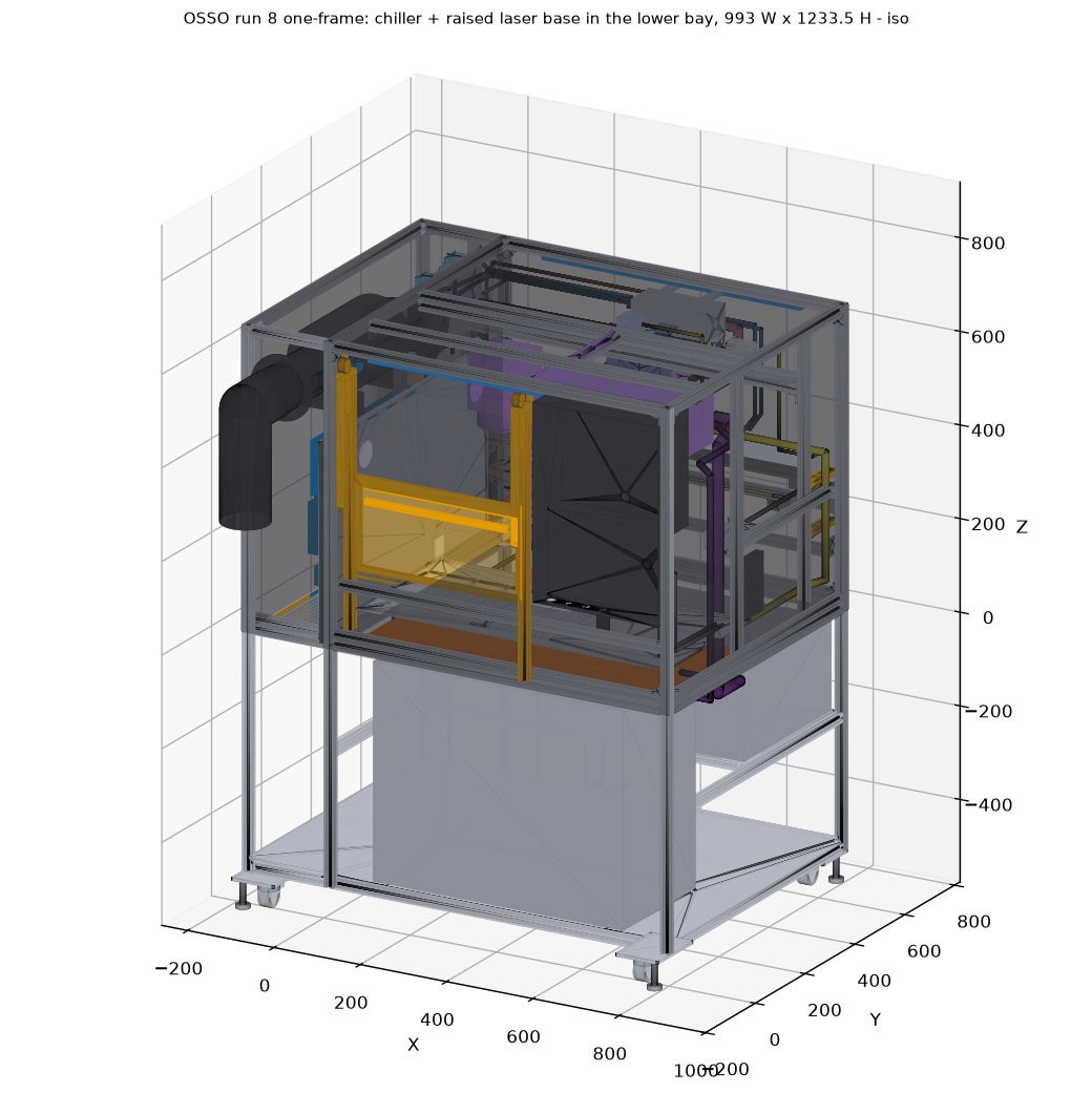
New in run 26: bigger trays, everything inside
One flexible tray system
The part trays now fill each side of the PCB pocket (102x162 and 269x162 mm). The same tray holds SMT or through-hole parts; its QR tag tells the software which layout is loaded.
Filter and lube inside
The positive-pressure filter unit sits on the front floor behind a louvre, and the optional one-shot lube pump sits in the electronics column. Nothing hangs off the outside.
Levels you can see
Flush tube vials on the front and both sides, all readable while you turn the feet. The model also marks the largest free space left below the laser.
See run 26: renders, animations and the model files · archive of earlier runs
What's in the machine
Laser, galvo and hood
A 10 W 355 nm UV pulsed laser with a galvo scanner and a 150 mm f-theta lens. The laser hood v1f hangs under the lens: a printed ASA galvo collar and adapter carry a formed 1.0 mm aluminium sheet shell (true bent sheet metal, inside bend radius 1.0 mm). A silicone band seals the hood on the PCB frame: tall on the one side that passes over the frame, low on the other three. The working distance is a parameter, 240 mm nominal. Since run 22 the laser sits at the rear and the hood drops 25 mm onto the PCB frame; since run 25 a fire watch on the duct can latch the laser off. The laser fires only when the hood is sealed.
Motion and tool head
A custom bed-slinger stage in 2020/2040 extrusion with MGN12 rails, a GT2-belt X axis and a twin tray. Head v5 rides the X/Z carriage with six cam-driven needles and a needle-sensor zone rule; heater plate v2 sits under the work area.
Enclosure v2
Clear 5.4 mm acrylic panels on a T-slot frame with M3/M5 hardware, so you can see the machine work. Printed ASA corner covers (R23.4) round off every edge. The 10.1 in touchscreen and all the controls sit in the front HMI pod.
Gull-wing door
A 708 mm wide clear door hinged at the top. It lifts 110° on two 80 N gas struts and seals on EPDM. Two coded interlock sensors cut the laser if it lifts 5 mm.
Swing-out electronics plate
The electronics sit on a plate behind the left door that swings out up to 180° on a front hinge, with a keyed latch and its own interlock. Mains enters on the back panel. Exact cable routing is still to be designed.
Leveling
Four M10 ball-swivel feet on 8 mm aluminium corner plates (58 mm nominal). Two glass vials clip onto the front bottom rail with a 45° mirror so both read from the front. An accelerometer on the electronics PCB gives a level check on the screen. A label reminds you not to lean on the machine.
Options OPTIONAL
These are designed in and shown in the renders, but they are optional: the machine works without them and either can be left out.
Positive pressure (optional)
A 92 mm filtered inlet fan (G4 + F7) at the top front of the electronics zone pushes clean air into the machine through a diffuser; the cabinet fans are reversed and a pressure sensor holds the enclosure slightly above room pressure to keep dust out.
Status light bar (optional)
A 700 mm light bar under the door shows machine state with distinct colours and patterns (Okabe-Ito colours, never red vs green). The touchscreen stays the main status display.
Where the design is
This is the run 26 model (Nov 2, 2026). Clash and clearance checks cover the door, e-plate, tray and hood paths and the head travel. See the run 26 machine page and the current state. Custom parts are FDM-printed, mSLA-printed or laser-cut only, so they can be made in a home shop or by common online services. Many values are still assumptions to check on real hardware.
A first build path
A simpler first build is planned: every safety item is always kept (door interlocks, E-stop, key switch, full enclosure, sealed laser hood, fume extraction, mains separation), while conveniences and the optional modules can be added later. The plan is to start with bench experiments on subassemblies before building the full machine.
Design process WORK IN PROGRESS
These pages document how OSSO is being designed. They are incomplete and change often; older pages describe ideas that have since been dropped.
- Development journal: day-by-day notes (381 entries).
- Version timeline: frozen snapshots (25 so far), with the latest version (v25).
- Decisions and design rules, to-do list, pending adjustments, references and tools.
Current model files (run 26 STEP, GLB, USDZ and the animations) are on the machine page. A full BOM and assembly directions will follow.